How To Wire A 2-Speed 230V Motor to a Hayward Pro Logic System

WRITTEN BY: 

  3.7 out of 5 stars on 10 ratings
(Click on a star to add your rating)

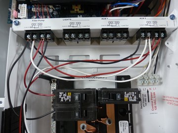
This guide will explain how to wire a 2-speed 230v motor to a Hayward Pro Logic. Before you start, you must ensure that the electrical supply agrees with the motor's voltage, phase, and cycle and that all electrical wiring conforms to local codes and NEC regulations. If you are unsure of this voltage or are unfamiliar with electrical codes and regulations, have a professional electrician wire your pump for you or at least check your work. Failure to wire the pump correctly can cause electrical shock or can damage your pump motor and void your warranty.

Click here to view replacement motors. 


Step by Step

Top

Step 1

Turn off the power to the Pro Logic at the main breaker.

Step 2

Step 3

Remove the three blue screws that secure the cover plate.

Step 4

Remove the cover plate.

Step 5

A 2-speed pump requires using two relays inside the Pro Logic box. Steps 6-9 explain how to connect those relays to the breaker.

Note - The breaker needed is a 20 amp 2-pole circuit breaker. We used a Square D HOM series breaker. Check the Hayward Pro Logic manual for a full list of acceptable breakers.

Step 6

Using black wire, connect one end to the bottom of the two-pole breaker and the opposite end to the first Line In spot on the Filter Pump relay.

Click here to view Hayward Pool & Spa Automation Systems. 

Step 7

Run a black jumper from the first line in spot on the Filter Pump relay to the first Line In spot on the Aux 2 relay. (You can use either of the Aux relays. We opted for the Aux 2)

Step 8

Using red wire, connect one end to the top of the two pole breaker and the opposite end to second Line In spot on the Filter Pump relay.

Step 9

Run a red jumper from the 2nd line in spot on the Filter Pump relay to the second Line In spot on the Aux 2 relay.

Step 10

Steps 11-16 will cover connecting the 2-speed motor wires to the Pro Logic relay. A 2-speed motor requires four wires; two hot wires, one common wire, and the ground wire. We’ll use black, red, white and green wires respectively.

Note - We used 14 gauge wire for this installation. Your installation may require a different gauge. Check out our recommended wire size chart for gauge requirements.


Click here to view Hayward Pool & Spa Automation Systems. 

Step 11

Cut the wires to a length that will reach from the motor to the Pro Logic. Add an extra foot or two just to be safe.

Step 12

The wire that we’ll use for high speed will be black. Connect the black wire to the second load out spot on the Filter Pump relay.

Step 13

The wire that we’ll use for low speed will be red. Connect the red wire to the second load out spot on the Aux 2 relay.

Step 14

The wire that we’ll use for the common line will be white. Connect the white wire to the first load out spot on the Aux 2 relay.

Click here to view Hayward Pool & Spa Automation Systems. 

Step 15

Run a white jumper from the first load out spot on the Aux 2 relay to the first load out spot on the Filter Pump relay.

Step 16

The wire that we’ll use for the ground is green. Connect the green line to one of the grounding lugs on the grounding bar

Step 17

Feed all four wires, from step 12-16, through one of the knockouts and through the conduit back to the motor. At this point, you can reinstall the Pro Logic cover plate.

Step 18

Loosen the two screws on the back cap of the motor and remove the cap.

Click here to view Hayward Pool & Spa Automation Systems. 

Step 19

Feed the wires through the conduit adapter at the motor.

Step 20

The following steps explain how to connect the wires to the motor. In our example, we are using a Century SQS1102R. Note: Not all motors are the same. Make sure you look at the wiring diagram on your motor label.

Click here to view the SQS1102R.

Step 21

Connect the black (high) line to the L1 terminal.

Step 22

Connect the white (common) line to the L2 terminal.

Step 23

Connect the red (low) line to the A terminal.

Step 24

Connect the green (ground) line to the green screw.

Click here to view Hayward Pool & Spa Automation Systems. 

Step 25

Replace the black motor cap and tighten the screws.

Step 26

Most pool pumps should be bonded. Connect the bonding wire to the bonding lug on the motor.

Step 27

Congratulations! You have successfully wired the 2-speed motor to the Pro Logic.

Comments

Top
(1 to 8 of 8)

 Posted: 8/24/2022 

My new Hayward 2 speed pump will only work on low speed. Any suggestions?
 Reply

InyoPools Product Specialist  Posted: 8/30/2022 

The most is most likely wored incorrectly, or there is a voltage issue. We go into detail on how to troubleshoot this issue in Pump Runs On Low Speed But Not On High Speed
 Reply

 Posted: 8/19/2022 

I’ve been doing repairs for over 20 years now, but haven’t messed with a two speed motor in awhile, and even longer since I had one wired to a ProLogic system, so a refresher was called for. This tutorial was perfect. I could not have explained this process more simpler than INYO pools has in this article. Well done!
 Reply

InyoPools Product Specialist  Posted: 8/30/2022 

Thank you very much. It truly is appreciated.
 Reply

 Posted: 8/7/2018 

Hello Roger - This is a hard question to answer without seeing the wiring diagram on the side of the motor. The diagram sticker found on the side of the motor should list the HI and LO wires next to the terminals. Not all dual speed motors are wired the same, which makes any answer without the diagram a guess.
 Reply

 Posted: 6/26/2018 

Would the "A" terminal on the pump in this guide be equivalent to the terminal 3 or 4 on a Pentair WFDS-28. They have the Terminal 1, 2, ground and terminal 3 or 4.
 Reply

 Posted: 6/9/2022 

The century motor I just pulled, 2 speed, 230v had 1,2,3&4. The new motor L1, L2 and A. This is a Hayward Super lol. I have had No luck with the new motor, it does not turn.
 Reply

InyoPools Product Specialist  Posted: 6/10/2022 

If the new pump accepts 230 volt and is a single speed, connect a hot wire to L1 and L2, and attach the ground wire o the green screw. Unless I am missing something, I am not sure why you would be having an issue with his installation.
 Reply