Pool pumps are wired to run on either 230V or 115V. Most are run on 230V and are preset at the manufacturers at 230V. If you are going to wire your own pool pump, you must first know what voltage is coming to your pump from the house circuit breaker. Also you must ensure that the electrical supply agrees with the motor's voltage, phase, and cycle and that all electrical wiring conforms to local codes and NEC regulations. If you are unsure of this voltage or are unfamiliar with electrical codes and regulations, have a professional electrician wire your pump for you or at least check your work.
Failure to wire the pump correctly can cause electrical shock or can damage your pump motor and void your warranty.


InyoPools Product Specialist Dennis R. Posted: 8/9/2015
myngos211 - A.O.Smith, now Century, stopped making adjustable Switches after November 2001, so chances are your switch is not adjustable. Check your wiring again to make sure you replaced the wires correctly and consider replacing the capacitor again. It may have been damaged by the spark show. See our guide on "How To Replace AO Smith Motor Parts - Overview" for where the wires should go. The guide also provides a link to “How To Replace the Start Switch on an AO Smith Motor”. Note: One of the yellow wire to the Switch has to be tucked away to keep it away from the spinning governor when the pump in on. That may be what caused the sparks.Reply
myngos211 Posted: 8/7/2015
Pretty good video. Question for someone. I replaced a bad capacitor with exact and pre-tested new one. Hooked up, tested without motor cap cover on, tested out and it ran fine. Proceeded to secure the capacitor with the bracket and put the motor cap on, hit the on switch and had a sparkfest going on. I checked and found a scraped wire which must've occured when I put the motor cap on. I replaced the wire and to do so I had to temporarily detach the start switch to run the wire behind it. Now when the motor is turned on, the motor turns but the start switch disengages and engages every 1/2 second or so. Is there an adjustment to be made to the stationary part of the switch? Or maybe I lost a leg of power?Reply
InyoPools Product Specialist Dennis R. Posted: 7/20/2015
Current - You may need a larger wire size between the pump and the circuit box for the higher current but it really doesn't make any difference to the motor which voltage/current you use. On startup, the higher amp draw can cause very brief lamp dimming if 115 is used.Reply
Anonymous Posted: 7/19/2015
What is the best current to run a Hayward Super Pump (energy, best life for motor, etc) if you have both 230 and 115 available?Reply
InyoPools Product Specialist Dennis R. Posted: 7/7/2015
lee - Generally the pool pump breaker will pop before the mail house breaker is activated and you will not have to reset both.Reply
lee Posted: 7/6/2015
If the breaker for the pool pump pops then do you have to reset the main breaker to the house or just the pool breaker to reset.Reply
InyoPools Product Specialist Dennis R. Posted: 7/6/2015
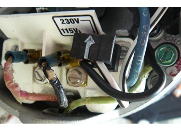
Randy - Usually, when a motor cycles on and off, it's because the motor voltage isn't configured the same as the supply voltage. Looking at the black plug, If you have 230V coming to the pump from the breaker, the black plug should only be connected to terminal 5 (see step #7). The right side of the black plug (white wire) is hanging off the end not connected to anything. If you have 115V coming in, the black plug is shifted to the left so that it is plugged into both terminals 4 and 5. You shouldn't have to change the inner wired (under the terminal block). Hope this helps.Reply
Randy Posted: 7/2/2015
First very helpful video you folks made in wiring the Hayward super pump. My question is, I up from a 1 horse to a 1 1/2 horse power super pump. After reading comments, I changed wiring from 12/2 to 10/2. My run is 80ft (less by 4ft) from breaker box to the pool switch. I hook up wires as shown and as you had shown, problem is it cycles on n off. Am going to change out the 30amp breaker its on and also haven't yet but will get a voltage meter to check. I did wire the motor direct, for a test, so from panel to the motor, I know not the wisest but wanted to see the result. Results were the same, cycle on and off. I then hook up the old pump (1 hp)and repeated it, wire direct from panel to pump, it run without a problem. Connections were tight on the motor 1 1/2hp. my 10/2 wire, white on the L1 left side, black on the L2 right side, then green ground screw. The motor wiring, black on the L2 4th and white/black strip on the 5th, far right side.I saw where someone said they inner changed wire locations, Ive held off on that idea. Thought I'ld seek your input first.
Randy..Culpeper, Va
Reply
InyoPools Product Specialist Dennis R. Posted: 6/27/2015
MARTIMP - Had a customer report the exact same error code. Turned out a couple of lizards [Florida] had gotten into the back of the motor and shorted out the capacitor and power terminal. Might check that first then call Hayward at 866-772-2100 for other suggestions.Reply
InyoPools Product Specialist Dennis R. Posted: 6/26/2015
adam - Not sure what your switch is doing. Check to see if your new motor is configured to run in 230V mode. If it is and your supply is 115V, you will have to reconfigure your motor for 215V.Reply
MARTIMP Posted: 6/25/2015
HAYWARD POOL PUMP w/ CENTURY 2 GREEN motor and timer, 2sp - 2hp, 230v, brand new installed, wired correctly, runs fine on low, runs for 3 seconds on high speed then kicks off with error message #7 (Overcurrent Fault: Remove power and rotate shaft, wait for max 1hr and take necessary action. It is due to locking of shaft) Shafts spins freely on low so please help with any ideas on a fix? thank you!Reply
adam Posted: 6/24/2015
I just bought a new motor for my inground pool , I have a 120 power source ( I checked with a volt meter) when I putThe switch on the back of the motor to 120..I think it actually says 115 but when I turned the power on the motor sounds like it's ceased ... when I put that switch on 230 mode it runs...should I be concerned with this or is it ok to run it on the 230 mode
Reply
InyoPools Product Specialist Dennis R. Posted: 6/23/2015
krmac - Make sure all your electrical connections are tight. Using a voltmeter, measure the voltage to your motor at the motor to make sure you are getting the correct voltage [I'm assuming you are set up for 115V since it is coming out of the wall]. Make sure your voltage is within 10% of 115V. That can vary during the day depending on your area and power company. Check the gauge of your wiring and length of wire going to your pump. You may be losing voltage in too small a line. See "Recommended Wire Size".Reply
krmac Posted: 6/22/2015
Question?I got a new motor (BV90) for my pump and attached it. From the wall plug, I put the black wire on the yellow wire connection and the red wire on the white wire connection (these are on the end of the motor). The green is attached the ground screw on the end of the motor. I ran it for a day and it was doing great. I turned off the pump, moved my filter to backwash and turned on the pump again, but nothing happened. The motor was hot and i'm concerned that maybe I put the wires to the wrong posts. How can I confirm? What else could be the issue?
Reply
InyoPools Product Specialist Dennis R. Posted: 6/18/2015
Lydiagirl - Here is a link to a 3-Prong Pump Power Cord w/ Twist Lock. You will have to rewire it to the back end of your pump.Reply
Lydiagirl Posted: 6/16/2015
I bought a 1.5hp above ground motor for my pool. My old motor had the twist lock safety plug. My new one does NOT. How can I change the plug on the new one to fit my receptacle. Help!!Reply
InyoPools Product Specialist Dennis R. Posted: 6/14/2015
Jeff - Your pump should be all right. 115V supply voltage going to a 230V configured motor is much more forgiving than putting 230V into a 115V motor.Reply
Jeff Posted: 6/14/2015
What kind of damage can be done if you forgot to switch the pump to 115? I have a 110 outlet and hooked up my new 1hp Hayward super pump, it ran for 5 minutes before shutting off. The casing was really hot and I finally saw i forgot to switch it to 115. Now it is running fine but don't know if those 5 minutes screwed something up on my new 500 pump.Reply
InyoPools Product Specialist Dennis R. Posted: 5/17/2015
Mike - There would be no difference. Power to the pump is a product of voltage and current. If you increase the voltage to 230V, your pump cuts the current (amps) in half. Effective power to the pump is the same.Reply
InyoPools Product Specialist Dennis R. Posted: 5/17/2015
pump/heater wiring - Usually the heater is connected to its own circuit. Was this how the pump and heater were wired before when the old pump was working? Try taking the heater off the pump circuit to see if the pump runs by its self. For wiring instruction, we have a list of owner's manuals by manufacturer. See if your owner's manual is in this list: Owner's Manuals.Reply
Mike Posted: 5/15/2015
Hello, I replaced 1 HP motor. Connected using 115 volts and set switch to 115 as it was. What would be the difference if I made it 230? Would it operate faster? Thank you.Reply
Anonymous Posted: 5/15/2015
I was asked by my neighbor to connect his pool pump for him this year. He has 230v out to the connection box. When I opened up the box, there were two single black wires with wire nuts on them, which matched the two single black wires coming from the pump. I connected them and the ground wire, flipped the switch and nothing happened. I took a meter reading on L1 to ground and L2 to ground. Both showed about 116v so I know the pump had power. As a result we believed the pump was bad. He bought a new one, connected it, and nothing again. Thinking about this, one thing I did notice is that the pump and heater are wired in series. Power goes from the box, through the pump, then through the heater, then coming out of the heater, it connects to a white wire. From black to white in that box I do read 230v. It seems strange to see the the pump and heater wired in series. In a typical pool pump circuit, are the pump and heater wired in series? I have looked for a wiring diagram on the internet, but have not found anything.Reply
InyoPools Product Specialist Dennis R. Posted: 5/12/2015
majordadto10 - Yes, that terminal board can be replaced. Here is the link to the Terminal Board.Reply
majordadto10 Posted: 5/12/2015
Can the terminal on the pump shown on steps 6 and 7 of http://www.inyopools.com/HowToPage/how_to_wire_a_pool_pump.aspx be replaced?Reply
InyoPools Product Specialist Dennis R. Posted: 5/11/2015
Webb - This switch is just interrupting the power from the breaker box. One wire goes to L1; the other to L2. There should also be a ground wire (green of bare) that should connect to the green grounding screw in the motor.Reply
Webb Posted: 5/11/2015
I bought your BN25 1hp 115v motor. I would like to add an on/off toggle switch. Where do I connect the 2 wires from the switch terminals to the motor? Thank you.Reply
InyoPools Product Specialist Dennis R. Posted: 5/9/2015
Geo - If you are wiring the pump for 220V, red goes to L1, black to L2 and the bare ground to the green ground lug. The white wire should not be attached to anything. Put a wing nut on it to be sure it doesn't short out other connections.Reply
Geo. Posted: 5/8/2015
I have four wires, black, red, white, and bare ground. The pool guy hooked it up, L1 red, L2 black, and the white to the ground. When I hooked up the exterior ground, it trips the breaker?Reply
InyoPools Product Specialist Dennis R. Posted: 5/2/2015
B-Rad - Even with the leads connected to the motor, they should still measure 240 volts across L1 and L2.Reply
B-Rad Posted: 4/29/2015
Okay thanks. I was wondering if it might be showing around zero because the meter was measuring the difference in voltage between L1 and L2 and since they are both 120, there wasn't any difference (120 = 120). Currently each leg shows 120 when measured to ground, but I may need to unhook both lines from the pump and verify that I still see 120 on each when measured to ground.Reply
InyoPools Product Specialist Dennis R. Posted: 4/29/2015
B-Rad - Something's wrong here. Are you sure you have 220V coming to the pump (two hot line)? If so, then when you measure voltage across L1 and L2, you should see around 240V. L1 to ground ~ 130V. L2 to ground ~ 130V. Voltage across L1 and L2 should never be 0V unless you have no power to the pump motor.Reply
B-Rad Posted: 4/29/2015
Hello,When I measure the voltage for L1 & L2, I typically leave the hot wires connected at the terminals on the pump and measure individually between L1 & ground and then L2 & ground. Is it possible that if one of the hot wires (say on L2) isn't getting power from the breaker that I could still be measuring 120 volts because L2 is somehow (within the motor) connected with L1? Should I be completely removing the 2 hot wires from the motor prior to measuring voltage? Also, am I correct in saying that using the voltmeter to measure between L1 and L2 should show approximately 0 volts?
Thanks in advance!
Reply
InyoPools Product Specialist Dennis R. Posted: 4/28/2015
B-Rad - Sounds good to me. L1 and L2 are common designators on a motor. As long as one wire is going to L1 and the other to L2, it doesn't matter that they don't go thru a terminal.Reply
B-Rad Posted: 4/28/2015
Hi!I'm set up for 230v, and have my 2 hot (110v) wires connected directly to the screws. In other words there was no wire terminal in which I could slip onto terminal 1 and 3. Thus I have one hot wire connected to the screw on L1 and another hot wire connected to the screw on L2. Is this okay?
thanks!
Reply
InyoPools Product Specialist Dennis R. Posted: 3/26/2015
Ken - Where is the other black wire going to? Is it unconnected? Just an extra wire. Is the white wire being used as the ground wire? It sounds like you can connect the black wire on the on/off switch [going to the pump?] to the black wire on the circuit breaker all right. I'm just not clear on the purpose of the other wire. Also if the red wire is connected to the switch and it also is connected to the power side of the circuit breaker, connecting the black wire to the switch would make this a 220V hookup and your pump should be configured for 220V. Have someone measure the voltage on the existing lines so that you can duplicate that hookup.Reply
Anonymous Posted: 3/25/2015
The underground galvanized 1/2" pipe that houses the wires connecting the pool on/off switch to the main circuit breaker has corroded...exposing four, # 14 solid copper wires. Pipe and wires are 51 years old. Nevertheless,the pool pump runs with no apparent wiring or connection difficulty. The above ground galvanized pipe is O.K.Only the below ground level galvanized pipe required removal.To replace only the underground pipe required cutting four wires on both ends.(two places). 1 wire is coded red, 1 wire is coded white and 2 wires are coded black.
My question only involves 2 black wires in the underground pipe.
Does it matter which of the 2 black wires in the underground pipe get reconnected to the 2 black wires protruding from the above ground piping?(both pipe ends).Can the black wire on the on/off switch end be switched to the black wire connecting to the black wire on the main circuit breaker end?
Ken
Reply
InyoPools Product Specialist Dennis R. Posted: 11/10/2014
m_farrell - You can plug this motor directly into a 110V outlet and you will have to switch the motor to 115V if it is currently configured for 230V. This switch is under the electrical cover.Reply
m_farrell Posted: 11/6/2014
Hi - I just bought a second Hayward in ground pump to use for a sump line for excess ground water behind the liner emergencies. I am going to install a pigtail or whip so I can plug this directly into a 110 outlet. Is that possible and if so does that mean I switch from 220 to 115 inside the cover? Thanks so much for your help.Reply
InyoPools Product Specialist Dennis R. Posted: 11/4/2014
Rick S - Sounds like your motor is wired correctly. I assume you have 230V supply power. Filters commonly run in the range of 5-15 psi when new or recently cleaned. And pump can run hot to the touch in some cases. See our guide on "How To Fix a Hot Pump Motor" for other considerations.Reply
Rick S Posted: 10/30/2014
I replaced my old 1 speed pump with a new Flotec 2 speed pump pre-wired for 230 operation. I attached a 110 lead to F-1 and the other 110 lead to F-2. Green wire attached to ground. Pump runs and is circulating water but will not build pressure greater than about 6 psi on the gauge. Motor also runs very hot to the point it is nearly too hot to touch the motor housing. I'm afraid to leave it running.Reply