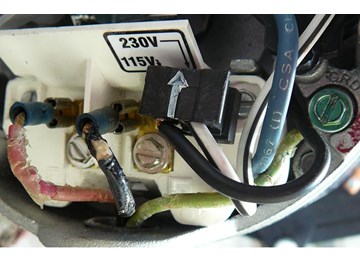
Pool pumps are wired to run on either 230V or 115V. Most are run on 230V and are preset at the manufacturers at 230V. If you are going to wire your own pool pump, you must first know what voltage is coming to your pump from the house circuit breaker. Also you must ensure that the electrical supply agrees with the motor's voltage, phase, and cycle and that all electrical wiring conforms to local codes and NEC regulations. If you are unsure of this voltage or are unfamiliar with electrical codes and regulations, have a professional electrician wire your pump for you or at least check your work.
Failure to wire the pump correctly can cause electrical shock or can damage your pump motor and void your warranty.


InyoPools Product Specialist Dennis R. Posted: 10/21/2014
Eric - I can't tell from your description how your system is wired, but if your look at our guide on "How To Wire a PE153 Digital Timer to a 2-Speed 230V Motor", you might get a better understanding of how 2-speed wiring works. Step 1 shows you the four connections for a 2 speed motor: "L1" goes to one side of the High Speed switch; "A" goes to one side of the Low Speed Switch; "L2" is the common wire to the other side of both the High and Low Speed switches; "G" is for ground. Now look at Step 3. It shows "L2" as the common line going to High and Low. It looks like if the wires to "L1" and "L2" were not as shown, the High and Low switches would not work. Try switching the wires to "L1" and "L2". Note: your wire colors are probably different from these.Reply
Eric Posted: 10/21/2014
Hello,I just replaced the two speed circulation pump on my hot tub. I labeled all of the connections and know that I didn’t make a mistake hooking it back up. When I turn it on it runs fine. However, when the system calls for circulation, the default speed is high when it should be low. The motor is single phase 115V and has four wires from the control panel, white, black, red and green. If I reverse the red and black will this change the default speed? I saw in other posts that changing red and black don’t make a difference but that was for two phase.
Reply
InyoPools Product Specialist Dennis R. Posted: 10/6/2014
Jon - The internal wiring does not have to match up with the external colors. If you have two terminals labeled L1 and L2, put the red wire from the house on one of these terminals and the black wire on the other. It does not matter which goes to which. Before you wire the motor, make sure that the supply power from the house matches the motor power configuration. If supply power is 220V, the motor should be set to receive 220V. If supply is 115V, motor should be set for 115V.Reply
Jon Posted: 10/4/2014
I have a new Oentair 2Hp pump; model # 2F345218. Replacing an old one, but the wiring looks a little different than the last purex Trton 2hp pump. The wiring terminals look the same, but not the wires. I'm trying to wire the new on, but it doesn't match Your diagram exactly. The pump came with the internal white wire already connected to one of the prongs on the L2 terminal. I have a red, black and green (ground) coming from the house. The green is obvious but I don't know where to connect the red and black. Also I can see an internal black wire in the pump,but it's connected internally. Please help. Thanks!Reply
Anonymous Posted: 8/30/2014
Really very helpful. Answered all of my questions in identifying how to wire my pump.Reply
wantabmacgyver Posted: 8/25/2014
This was a lot help of for novice, saved us hundreds of dollarsReply
InyoPools Product Specialist Dennis R. Posted: 7/25/2014
Colin - When you change speeds, you are actually switching between two circuits. One of the wires in this circuits is common to both circuits and that may be what they are referring to as the “common wire”. Here's a link to an example of how to wire a two speed pump to a 2 speed timer: http://www.inyopools.com/HowToPage/how-to-wire-a-pe154-digital-timer-to-a-2-speed-230v-motor.aspx . In step three, the "common wire" is attached to L2.Reply
InyoPools Product Specialist Dennis R. Posted: 7/25/2014
Joe - I don't see any information in our system on your pump. Usually the motor label has a picture on the motor label that shows how to change from 230 to 115 but they may not have started that til after your pump was built. If you haven't done so already, I would suggest looking on the internet for information on your specific model.Reply
Colin Posted: 7/24/2014
I have a Pentair 2 speed 115v pump with 3 terminals - common, high and low. The wiring diagram with my controller (TightWatt2) is telling me to connect the load to the common and the neutral via a switch to high and low. Am I reading this correctly? I always thought common was neutral?Thanks
Reply
joe Posted: 7/24/2014
Your blog is wonderful and very helpful.however I have a problem that maybe your readers might have some insite into.
I have a 1997 jacuzzi fet pump model R7CJC with an emerson motor C%%CXHRT that was never used. it has a 230/225 switch inside that I moved from the preset 230 to the 115. There are 2 prongs on the 115 that are vacant. There is no diagram other than one that shows two wires and the switch and to "line" Connectors. there is a note that the instructions should be read before changing voltage. However I dod not have any documents. I tried the 230 volts first and the motor works, but I can not get the 115 volt to work. I understand you do not have such old documents, but you readers might Any orther helpful suggestions? please
Reply
InyoPools Product Specialist Dennis R. Posted: 7/20/2014
Rick B – Have someone check the voltage going to you pump and make sure it is the same as what your pump is set up for. There should be instructions on the motor label that show you how to set your pump’s voltage.Reply
RickB Posted: 7/19/2014
I replaced my Hayward Super Pump with a Century Centurion (PacFab-Challenger). The wires from my pole house are Red, White and Green. The wires from the PacFab are Black, Black and White. In order of wires from source to pump, do I connect the Red to Black, White to Black and Green to White (Ground Wires)? Is my wiring 230 or 115? Need help, pool is getting greener by the day. (New Orleans HEAT)Reply
InyoPools Product Specialist Dennis R. Posted: 7/17/2014
Matt - The only difference between impellers for a given pump is the diameter. And you can't go by the diffuser. The same diffuser can be used for several impellers. Look at the HP and SF values on the label of your motor. Multiply them together to determine your motor's real or total HP (THP). Find your pump on our web site and look under replacement parts for the impeller that should be used with that THP. Or give us a call at 877-372-6038 and we will walk you through it. Another thing to look at: if you have an above ground pool, make sure the extension cord is heavy enough to carry the pump's current.Reply
Matt Posted: 7/16/2014
Thanks for the quick reply. I used an impeller that was recommended by our local pool supply house. It looked to be the same diameter as the previous impeller and fit perfectly with the diffuser. I assume that diameter is the concern? Or is there a different impeller vane pattern that I need to look at?Reply
InyoPools Product Specialist Dennis R. Posted: 7/16/2014
Matt - Check to make sure your new impeller is not too large. If you have the wrong impeller and it is larger than specified, your pump's motor will be trying to move more water than it is capable of handling and will overheat. If you selceted the impeller listed for a full rated 1.0 motor and you have a 1.0 uprated motor, you may have the wrong impeller.Reply
Matt Posted: 7/16/2014
I just changed out the impeller and diffuser on a PacFab pump, reinstalled and had the motor overheating. I replaced the motor with a brand new unit and it overheated in about a hour. All suction and discharge lines look clean and nothing has changed with the pool valving since the impeller was swapped out. Motor is AO Smith 1 HP, 230V single phase. All wiring and voltage is good. The previous owner did not have the bonding wire attached, could that cause the motor to overheat?Reply
InyoPools Product Specialist Dennis R. Posted: 7/15/2014
Jeff - The motor label should have instructions in one of the corners on how to change the motor's voltage. Not sure that is your problem though. If your motor is set at 220V and your supply voltage is 115V, your motor would generally cycle on and off every 5 minutes. Make sure you replaced the motor with one of equivalent total HP. Your motor's "real" HP is determined by multiplying its HP by its Service Factor (SF) – see motor label. For example a motor with HP = 1.0 and SF = 1.5 has a real HP of 1.5. A motor with HP = 1.0 and SF = 1.0 has a real HP of 1.0.Reply
Jeff Posted: 7/14/2014
I bought a centurion BPA450 - 230/115..and it barely pumps water on 115v. I had an old 1hp gen run on 115v for 20 years and it pumped great till it finally died.You mentioned that most generators are PRE-SET to 220v...
How do I change it to accept 115v....
Reply
InyoPools Product Specialist Dennis R. Posted: 7/14/2014
Terry - I've been told by the motor experts that a pump motor cannot run backwards. If water is coming into the front of the motor through the strainer basket, you may just have the hoses reversed. Check that the hose from the skimmer is going to the input at the pump's strainer basket.Reply
Terry Posted: 7/13/2014
got a replacement pump , hook ups are right runs great , only thing is it is running backwards , not sucking water in pushing it out . don't know why . help.Reply
InyoPools Product Specialist Dennis R. Posted: 7/13/2014
zak56 - It does not matter. With AC current, they are interchangeable. The beige wire can be attached to either L1 or L2. Blue goes to the other.Reply
zak56 Posted: 7/12/2014
All the tutorials I read talk about black, red, and green wires. My pool pump stopped working and I took it off and brought it to the pool place nearby. They were thankfully able to fix it. I've brought it home and like a dummy I did NOT take a picture of where my wires go. My wires are green (ground), beige, and blue. Does anyone know which wire goes to L1 and which one goes to L2 (beige or blue??)??Thanks for help!
Reply
InyoPools Product Specialist Dennis R. Posted: 7/1/2014
noble - Check your supply voltage. Make sure that it is the same as what your pump is set up for. Motors do have an overload protector that shuts off when the motor overheats, but it resets itself when the motor cools. If you have an above ground pool, make sure the extension cord is not too long and is heavy enough to carry the current to the motor.Reply
comet65 Posted: 6/30/2014
Thank you! Thanks to you, my new pump is up and humming. Thought I'd even add a GFCI, for good measure; maybe now I'll get to meet my grandkids. :-)Reply
noble Posted: 6/30/2014
I have a whirlpool that was put in when I turned it on it lasted 10 min's and has sense stopped working, I was wondering if the motor had a reset button it, the barker's look fineReply
InyoPools Product Specialist Dennis R. Posted: 6/25/2014
bilbander - Yes, I would change your breaker from 15A to 20A. And probably change to a heavier cord to make sure your pump is getting full voltage.Reply
bilbander Posted: 6/24/2014
I could get a heavier cord but I think the main box has a 15 amp would not just shut off there, is it advisable to change that to a 20amp.Reply
InyoPools Product Specialist Dennis R. Posted: 6/24/2014
bilbander - If you are using 115V supply power, you pump is using 16.5 amps which is a little higher than your 15 amp breaker. You may need a higher breaker. If you are using a long extension cord, you may have to go to a heavier duty cord. Sounds like the wiring on your pump is correct. For AC power, it doesn't matter how the white/black wires are connected to the L1 and L2 terminals. Make sure the terminals connections are tight.Reply
bilbander Posted: 6/23/2014
Lost my comment?So when changed to the digram it doesn't work.
I do not have copper connections and have three copper wires spliced to bond it.
Hope you see my old comment
Bill
Reply
bilbander Posted: 6/23/2014
Hi I installed a Hayward max-flo ll pump 1.5 hp 16.5/9.2-8.5 amps.I ran it all season two years ago with no problem lever used it last year plugged it into the same ext cablke this year it spark and rubber burned at the plug. It will run half an hr then trip the 15 amp on the plug.I cleared the filter and it ran all day.added my filter product and it trips every 1/2hr it also trips when I just run it as a recycle. I thought the wire was not thick enough and it was over loading but when it us just recycling there is no real load.
I have a black/white/and green on my short extension into the pump.
I tried attaching white to L1 and the black onto L2 but it does nothing.
Reply
InyoPools Product Specialist Dennis R. Posted: 6/23/2014
Rick - This is AC current so it does not matter how you attach the red wires to your pump's terminals. The pump cannot be wired to run backwards.Reply
Anonymous Posted: 6/23/2014
I have 3 wires going to the existing booster pump. The ground is green and 2 other red wires, After replacing the gasket and attempting to reattach the wires on the pump, I am thinking the two red wires are reversed which possibly reverses the direction of the impeller? Does it matter which way to reinstall the 2 red wires?The pump sounds louder and does not seem to be pumping.
The other possibility is the pump did not prime, but i did not want to run it sucking air.
Thank you in advance for your opinion.
Rich
Reply
InyoPools Product Specialist Dennis R. Posted: 6/17/2014
mark - The part number 94027120 links to a Jacuzzi Magnum Force Pump. It can be wired for either 115V or 230V. These voltages can vary 10% so 220V and 230V are equivalent. Here's the specs on that motor: "Jacuzzi Magnum Force". The owner's manual says that wiring instructions are on the motor label. For further information call Jacuzzi/Carvin at 450-250-4500.Reply
mark Posted: 6/16/2014
I old jacuzzi magnum pump 2.0 hp. just quit, I am thinking about ordering the jacuzzi magnum part. 94027120 looks like the intake and outtake should line up on the plumbing, is the new pump a 230v and I know my old one was one what i thought was 220 but must be 230v. doesthis pump have instructions on how to wire ?
Reply
InyoPools Product Specialist Dennis R. Posted: 6/9/2014
Peter P - There should be L1 and L2 labels on the terminal that the white, brown and black wires connect to at the pump. Your red and blue wires would go to L1 and L2. If the terminal is not labeled, give Speck a call at 800-223-8538 for instructions.Reply
Peter P Posted: 6/6/2014
I have three wires for 230 volts from timer, the colors of the wires are green, red and blue. I have a Stark Pump Model 75035 which has been factory connected for 230 Volts. At the terminal of the pumps there are white, brown and black wires. The instruction is not specific. How do I connect the input wires to the pump terminals?Reply
InyoPools Product Specialist Dennis R. Posted: 6/6/2014
Big Joe - If your old pump was 220V, you can assume that the supply voltage is 220V. The Black and Beige wires are both hot and you do not need a neutral wire. I assume your speed switch takes care of switching between high and low RPM and that function does not require a different timer.Reply
BigJoe Posted: 6/4/2014
.....Just to add... The current black and beige wires are connected to L1 and L2 on the old single speed, 2HP Hayward pump.Reply
BigJoe Posted: 6/4/2014
Hello. I just bought a Hayward 2hp 2 speed pump (it has a speed switch on it). My current Hayward 2hp single speed pump has a 220V connection, which plugs into my timer panel (there is a 220V female connector installed in it). The wiring running to the existing pump has Green, Black and Beige wires. Should I assume that the Black and Beige are hot? No red wire at all. Do I need a common wire? Thanks.Reply
InyoPools Product Specialist Dennis R. Posted: 6/3/2014
Jandy pump wiring - Sounds like you are wired correctly. Terminals 1 and 2 are tied to L1 and terminals 3 and 4 are tied to L2. They just offer another option to connect to L1 and L2.Reply