Hello everyone,
I recently purchased a replacement two-speed motor. The wiring set up is slighlty different from the original motor, so rather than make a mistake, I thought I would ask the experts for some guidance on what appears to be a simple issue. I am attaching 4 images to explain the issue clearly. Any assistance is greatly aprpeciated. Thank you in advance.
Image 1 is of the original motor wiring diagram. It has terminal numnbered 1, 2, and 4 as shown.
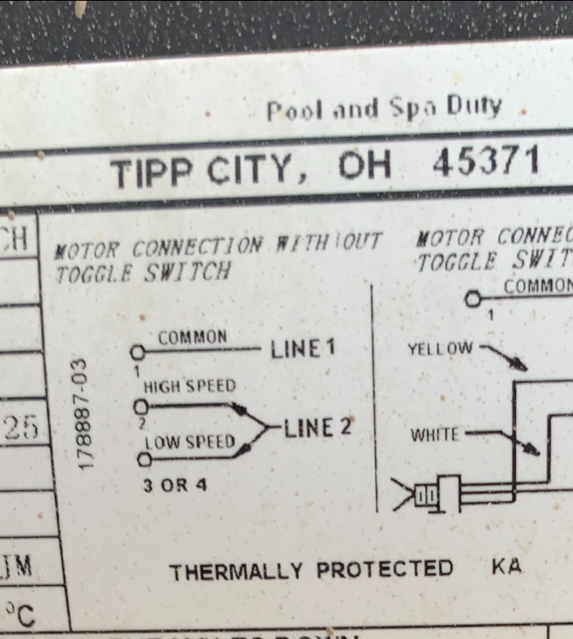
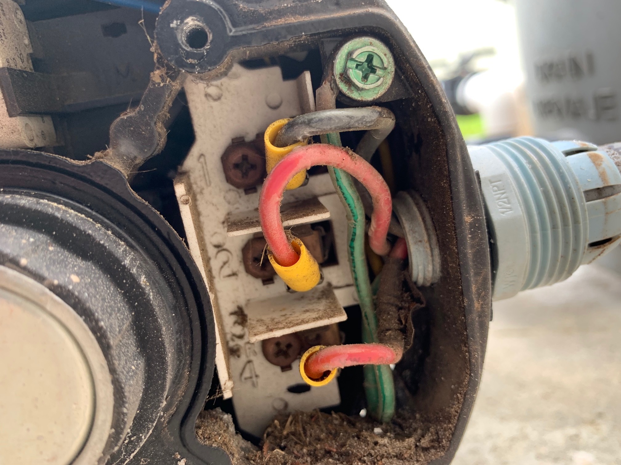
Image two shows how the original motor was wired.There are three wires, one black and two red wires. One of the red wires has a piece of black electrical tape aroudn it to distinguish from the other red wire. The single red wire without the electtrical tape is connected to terminal #2 on the motor and runs into the timer that is labeled lowspeed. The Black wire is attached to terminal # 1 and the other Red wire with the black tape is connected to terminal 4. Both of those wires run into the other timer unit. Please see the picture below.
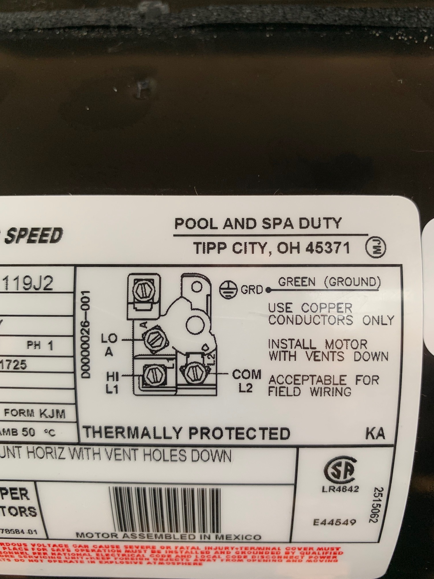
The new motor has a slightly labeling as shown in the follwoing picture.
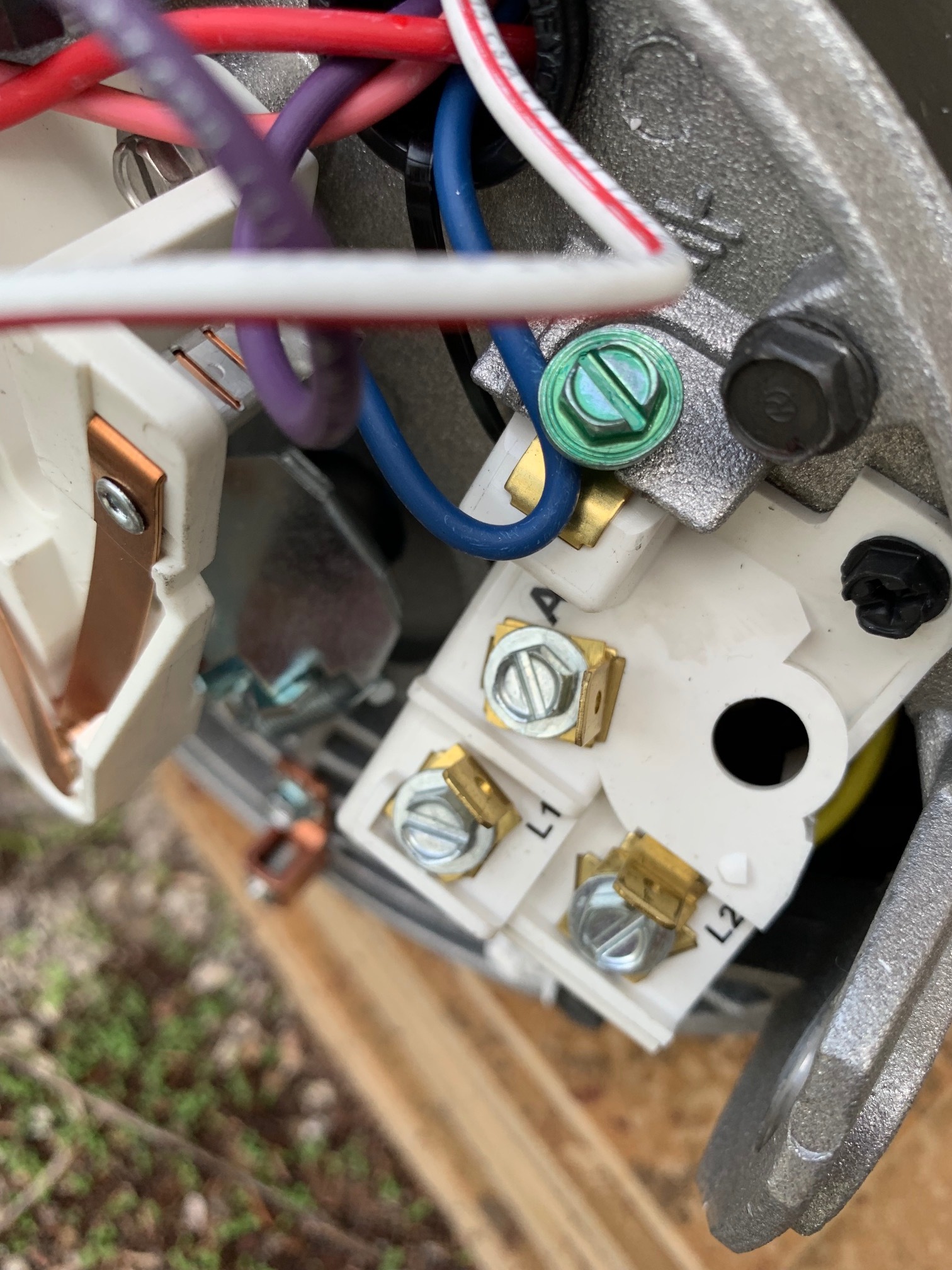
So, I need to know which wires goes to which terminal.
Black goes to ? A, L1 or L2
Red goes to? A, L1 or L2
Red with Electrical tape goes to? A, L1 or L2
Please see image below
I appreciate any feedback you can provide. Thank you.