How To Use a Multimeter to Test a Pool Pump Motor - Winding Resistance

WRITTEN BY: 

  3.47 out of 5 stars on 15 ratings
(Click on a star to add your rating)

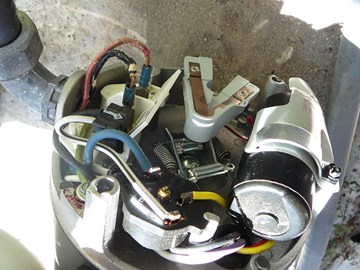
A common Capacitor Start Pool Motor has three sets of windings: two sets of main windings which are engaged while the motor is running and a third Capacitor winding that provides extra torque in the motor during its initial startup. This guide shows you how to measure the resistance in these coils to determine if this is the cause of a failed motor. MAKE SURE THE POWER IS OFF before you take these measurements.

Click Here to View Motor Parts (Including Capacitors, Bearings, Switches & More)

Click Here to Find Your Replacement Pool Pump Motor & Gasket Kits

Step by Step

Top

Step 1

THE ISSUE - Your pool pump motor won't rotate under power but the shaft turns freely. What is the problem? A motor has several electrical components that might fail: start capacitor; overload protector; power terminal; loose wires; and motor windings. . This guide shows how to measure the motor windings to eliminate them from further consideration.

Click Here to View Motor Parts (Including Capacitors, Bearings, Switches & More)

Click Here to Find Your Replacement Pool Pump Motor & Gasket Kits 


Step 2

SET MULTIMETER - One of your first steps is to obtain a multimeter and to set it on its lowest resistance (R) setting.

Step 3

TURN OFF POWER - Make sure to TURN OFF POWER to your pump before opening up the electrical end of the pump. You will probably be working with 240V so be careful. If you are not familiar with electricity, have an electrician help you. Turn off the power at the circuit breaker to the pump for maximum protection.

Step 4

REMOVE ELECTRICAL COVER - Unscrew the two screws that hold the cover over the back end of the motor. Remove the cover to expose the electrical connectors.

Step 5

SHORT OUT CAPACITOR - Pool Pump Capacitors store an electrical charge that can shock you even when the power is off. Before removing the capacitor, discharge this energy by placing an insulated screwdriver across the leads of the capacitor. CAUTION: Capacitors have been know to explode when shorted out. For your protection wear eye protection and place a cloth over the capacitor before shorting it out.

Click Here to View Motor Parts (Including Capacitors, Bearings, Switches & More)

Click Here to Find Your Replacement Pool Pump Motor & Gasket Kits

Step 6

WIRING DIAGRAM - This picture shows the location of the winding circuits that you will be measuring. There are three sets of windings: the main windings are split into two sets, shown in the green box; the auxiliary start capacitor winding is shown in the red box. The start capacitor winding provides extra torque during the initial startup of the motor to help prime the pool system. In general, you will be taking 4 readings. You will be comparing the resistance readings of one set of main windings against the other, Then you will be comparing the resistance readings of one set of main windings plus the start-up windings to the other set of main windings with the start-up windings. The measurement points are identified by blue circles. They include: the "L2" power terminal; the "A" power terminal; the yellow wire attached to terminal 3 on the Overload Protector, and the end of the red lead going to the switch. For these measurements the red lead to the switch must be detached to simulate and open switch.

Step 7

WIRING - This picture shows the physical layout of the wiring circuits. Some of the components have been moved to better show the wires. The four measurement points identified above are also highlighted on this picture with blue circles.

Step 8

REMOVE RED LEAD TO SWITCH - With a pair of needle nose pliers, take the red wire off of the switch. The switch is normally closed when the motor is not running. You want to simulate an open switch when you take these measurements.

Step 9

L2 to A - To test the lower main windings, place the meter probes on L2 and A on the power terminal. Record the reading.

Click Here to View Motor Parts (Including Capacitors, Bearings, Switches & More)

Click Here to Find Your Replacement Pool Pump Motor & Gasket Kits 


Step 10

LOWER MAIN WINDINGS - This picture shows the part of the electrical circuit that is included in this measurement - between L2 and A.

Step 11

A to YELLOW - To test the upper main windings, place the meter probes on A on the power terminal, and on the end of the yellow wire attached to terminal 3 of the Overload Protector. Record the reading.

Step 12

UPPER MAIN WINDINGS - This picture shows the part of the electrical circuit that is included in the above measurement - between A and Yellow.

Step 13

COMPARE READINGS - Compare the reading taken above for the upper main windings and the lower main windings. They should be the same. If no, you will probably need to replace the motor.

Click Here to View Motor Parts (Including Capacitors, Bearings, Switches & More)

Click Here to Find Your Replacement Pool Pump Motor & Gasket Kits

Step 14

YELLOW TO RED - To test the upper main windings including the start capacitors windings, place the meter probes on the end of the red lead, and on the end of the yellow wire attached to terminal 3 of the Overload Protector. Record the reading.

Step 15

UPPER MAIN WINDINGS & START WINDING - This picture shows the part of the electrical circuit that is included in the above measurement - between Red and Yellow.

Step 16

L2 to RED - YELLOW TO RED - To test the lower main windings including the start capacitors windings, place the meter probes on the end of the red lead, and on L2  on the power terminal

Step 17

LOWER MAIN WINDINGS & START WINDINGS - This picture shows the part of the electrical circuit that is included in the above measurement - between L2 and Red.

Step 18

COMPARE READINGS - Compare the reading taken above for the upper main widnings plus start windings, and the lower main windings plus start windings. They should be the same. If not, you will probably need to replace the motor.

Click Here to View Motor Parts (Including Capacitors, Bearings, Switches & More)

Click Here to Find Your Replacement Pool Pump Motor & Gasket Kits 


Comments

Top
(1 to 19 of 19)

 Posted: 7/25/2022 

Good evening. Is it possible to reverse rotation on this motor? If so, can you please draw a diagram on how this is done. Thank you.
 Reply

InyoPools Product Specialist  Posted: 7/28/2022 

Unless the motor is three phrase, you cannot reverse the rotation.
 Reply

 Posted: 3/15/2021 

Thank you for the article--very informative. What does it mean when all of the resistance readings (L2 to A, A to YELLOW, YELLOW to RED, and L2 to RED) are all "OL" (open circuit--no continuity)? I have a Hayward 6060 booster pump that stopped working. The circuit breaker was tripped so I reset it, and it trips immediately (with a loud pop) when the pump is turned on. I'm guessing the motor windings are shot, but I can't figure out why ALL of the readings would show OL. Thanks.
 Reply

 Posted: 5/19/2021 

Dean, my motor does the same thing. It rained heavy last night and the pump made a ‘pop’ sound and tripped the breaker. Was your motor dead or was it a wiring issue? I’m thinking the wires shorted or arc’d on mine due to rain.
 Reply

InyoPools Product Specialist  Posted: 5/21/2021 

Whatever the cause, the circuit is getting wet and becoming compromised which means it should be inspected.
 Reply

InyoPools Product Specialist  Posted: 3/16/2021 

I would hazard a guess by saying that your motor is just dead, and the wiring and windings are shot. If a motor is that bad off, a post-mortem isn't really necessary, it just needs a replacement.
 Reply

 Posted: 11/15/2020 

How do you check the windings on a U.S motors 1081 pump ? Cat.EUSQ1102. The capacitor tests good , the motor shaft turns easily and the motor hums and than turns off the breaker? What the problem? . Motor does not smell burnt?
 Reply

InyoPools Product Specialist  Posted: 11/16/2020 

It would be the same process for checking most 1081 single speed pool pump motors. The designs across the various manufacturers are very similar. Follow the steps in this guide, and you should be successful.
 Reply

Anonymous  Posted: 11/16/2020 

I would agree If the voltage switch and wire colors where the same as in your description. On the US motor they are completely different. If you could post with pictures the solution , It would be greatly appreciated .
 Reply

InyoPools Product Specialist  Posted: 11/18/2020 

Unfortunately, we have never carried US Motors, so a library of their how-tos and schematics is not something I have on hand. You want to reach out to US motors or one of their retailers for guidance on this specific troubleshoot.
 Reply

 Posted: 10/9/2018 

The reading: Main winding + start capacitor winding, does it assume the capacitor is good?
 Reply

 Posted: 7/22/2019 

For the benefit of those reading in the future, the 2 yellow wires are on the same post of the cap. so the cap. isnt in the circuit.
 Reply

InyoPools Product Specialist  Posted: 10/10/2018 

Hello Raul - presumably you would have checked the capacitor before getting to this point of breaking down the motor to check the windings. But if you haven't, I suggest reviewing this guide: How to Test a Pool Pump Capacitor
 Reply

InyoPools Product Specialist  Posted: 11/7/2016 

Kerim - The most common electrical problem is a bad capacitor. Check that first is you haven't. Then look at our guide on "How To Replace AO Smith Motor Parts - Overview" for other suggestions. If no luck there, I'd pull the motor out and have a pool or motor store look at it.
 Reply

 Posted: 11/6/2016 

I've done all these electrical tests. All are fine, but still my pump doesn't start! It even doesn't hum! What is the issue?
Appreciated your help

 Reply

 Posted: 10/29/2016 

Thank you for the simple guide and it make work so interesting and confident when facing such matters. Appreciate on the guide.
 Reply

InyoPools Product Specialist  Posted: 7/21/2016 

Winding Resistance - The red wire to the switch is disconnected during all tests. It just looks like it is connected because it is near the switch terminal.
 Reply

Anonymous  Posted: 7/19/2016 

Looks like the red wire was reconnected to its terminal, but I don't see where this happened. Which tests should have this disconnected?
Thanks!!

 Reply

 Posted: 3/8/2016 

Great explanation
 Reply