How to Wire 115V Equipment to the Hayward Pro Logic

WRITTEN BY: 

  4.5 out of 5 stars on 2 ratings
(Click on a star to add your rating)

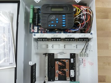
This guide will explain a how to wire a 115v piece of equipment to the Hayward Pro Logic. This includes items like a single speed pump, booster pump, blower and salt chlorine generator.

Note - Items like gas heaters and heat pumps are controlled via 24v by the Pro Logic. They are not to wired to the Pro Logic for power. Do not attempt to use this guide in order to power the gas heater or heat pump.

If you're not experienced working with electricity, we strongly recommend contacting an electrician.

Step by Step

Top

Step 1

Turn off the power to the Pro Logic at the main breaker.

Step 2

Open the door to the Pro Logic box.

Step 3

Remove the three blue screws that secure the cover plate.

Step 4

Remove the cover plate.

Step 5

Determine the relay and breaker you'll be using. A single speed pump would use the Filter Pump relay. Anything else can use one of the Aux relays.

The breaker we used was a 20 amp single pole Square D HOM series breaker. Check the Hayward Pro Logic manual for a full list of acceptable breakers.

Step 6

Using black wire, connect one end to the single pole breaker and the opposite end to the first Line In spot on the Filter Pump or Aux relay.

Note - We used 14 gauge wire.

Step 7

Steps 8-12 will cover connecting the 115v equipment wires to the Pro Logic relay. A 115v product requires three wires; one hot wire, one neutral wire and the ground wire. We’ll use black, white and green wires respectively.

Step 8

Cut the wires to a length that will reach from the 115v item to the Pro Logic. Add an extra foot or two just to be safe.

Step 9

Connect the black wire to the first Load Out spot on the Filter Pump or AUX relay.

Step 10

Connect the white wire to the neutral bar to the left of the breakers.

Step 11

The wire that we’ll use for the ground is green. Connect the green line to one of the grounding lugs on the grounding bar.

Step 12

Feed all three wires, from step 8-11, through one of the knockouts and through the conduit back to the 115v item.

Step 13

Place the cover plate back on the Pro Logic box and tighten the three screws.

Step 14

At this point, you'll need to look at the wiring diagram of the item that you're connecting to the Pro Logic. The wiring diagram should describe where to connect the ground and hot lines.

Comments

Top

Be the first to add a comment