How To Wire a PE153 Digital Timer to a 2-Speed 230V Motor

WRITTEN BY: 

  3.58 out of 5 stars on 12 ratings
(Click on a star to add your rating)

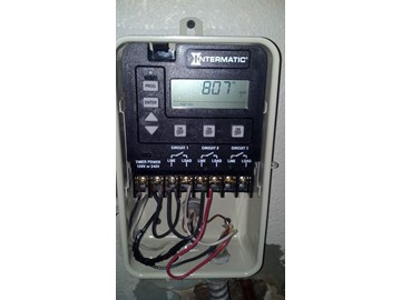
This guide shows you how to wire the basic functions of a PE153 Digital Timer to a representative 2-speed 240V motor. It is fairly simply but it requires an extra wire to be able to switch between a low speed circuit and the high speed circuit. If you are going to wire your own pool pump, you must first know what voltage is coming to your pump from the house circuit breaker. Also you must ensure that the electrical supply agrees with the motor's voltage, phase, and cycle and that all electrical wiring conforms to local codes and NEC regulations. If you are unsure of this voltage or are unfamiliar with electrical codes and regulations, have a professional electrician wire your pump for you or at least check your work. Failure to wire the pump correctly can cause electrical shock or can damage your pump motor and void your warranty.

Step by Step

Top

Step 1

VIEW MOTOR TERMINALS - A typical single speed pool motor has three terminals: "L1", "L2" and Ground. Most 2-speed motors have four terminals: "L1", "L2", Ground, plus "A", to allow for switching between the high and low speeds of the motor. "L1" and "L2" provide the "High" speed circuit; "A" and "L2" provide the "Low" speed circuit. Because "L2" is used in both circuits it is commonly labeled "line" for common line. This picture shows the location of the four motor terminals for the 2-speed motor. Four wires will come from the timer to these terminals as shown. The wires are color coded to show how each connects to the timer. The "W'" embedded in the "L1" line indicates a white wire. This motor is designed to run only on 230V. If your motor is designed for 120V or 230V, make sure it is configured for the supply voltage (from the house circuit board) that you will be using.

Step 2

VIEW TIMER TERMINALS - The PE153 Digital Timer can accommodate 3 circuits as shown in this picture. You will be using two of these circuits for your 2-speed motor: Circuit 1 will control the "High" speed of the motor and Circuit 2 the "Low" speed. Circuit 3 is extra and can be used to control any other pool function like controlling your pool lights. The Timer has 8 terminals as shown at the bottom of this picture. Terminals 1 and 2 are connected to the supply lines from the circuit breaker. For 230V either line can be placed on either terminal. A volt meter placed across 1 and 2 after wiring will read around 230V for 230V supply. Terminals 3 and 4 provide the high speed circuit. Terminals 5 and 6 are allocated to the Low speed circuit.

Step 3

VIEW WIRING DIAGRAM - This picture shows a simplified wiring diagram for the PE153 Timer and the 2-Speed Motor. The Timer connections are at the top; the motor connections at the bottom. Supply Power is shown coming in from the top and connecting to terminals 1 and 2. Either wire can go to either terminal. The black line from "L2" on the motor is connected to terminal 1. The front sides of circuits 1 and 2 are powered by connecting jumper wires from terminal 2 to terminal 3 and then to terminal 5. Connect the "L1" white wire from the motor to terminal 4 to complete circuit 1, the High speed circuit. Connect the "A" red wire from the motor to terminal 6 on the Timer to complete circuit 2, the Low speed circuit. Finally connect the ground wire from the motor to the timer ground.

Step 4

VIEW TIMER CONNECTIONS -  This picture shows the actual Timer connections in accordance with the wiring diagram. Lines labeled "S" are the Supply Lines; "J" lines are jumpers; Motor lines are "L1", "L2", "A", and "GRD". Circuit 1 (High) and Circuit 2 (Low) are opened and closed through programming or by pushing the manual ON/OFF buttons above each circuit. See your user's manual for programming instructions.

Step 5

CHECK POWER SWITCH - There is a power switch on the back side of the Timer panel. Make sure the switch is set to the 240V position for this configuration. This assumes that the supply voltage and motor configuration are 240V. If your motor is configured for 120V, your supply voltage must be 120V and this Timer power switch has to be set for 120V. If the voltage switch is in the wrong position, the Fuse (next to the switch) will blow and you may cause damage to the circuit board voiding the manufactures warranty.

Step 6

SET MODE - The PE153 Digital Timer can operate in one of 5 modes. Mode 1, for example, would be used to control any three independent circuits. A 2-speed motor will use mode 2. To set the Timer mode, use a small tool to press and hold the mode button for 5 seconds. Push the Up or Down arrow keys until Mode 2 is displayed. Then push the Enter key. "Mode 2" should remain displayed at the left side of the screen.

Step 7

PROGRAM TIMER - See your User's Manual for detailed instructions on programming the Time clock and circuit on/off times.

Comments

Top
(1 to 6 of 6)

 Posted: 2/13/2022 

I’ll be wiring for a 2 speed pump. How do I wire in the pool heater. Thanks
 Reply

InyoPools Product Specialist  Posted: 2/14/2022 

A heater is a basic two-line circuit; it would be connected to one of the 3 available circuits on the PE153. Refer to the PE153's Owner's Manual on pages 16 thru 18 for wiring instructions
 Reply

 Posted: 2/14/2022 

Thanks for your answer about my wiring a 2 speed pump with a heater. Confused as to which mode to use on the P135ME. Thanks so much.
 Reply

InyoPools Product Specialist  Posted: 2/14/2022 

Well, if we look at the manual for the P135ME on page 25, it shows the way to set up Mode 7. 
 Reply

 Posted: 4/18/2019 

Thanks guys! I had the pump wired wrong and thanks to these instructions I got my new pump going!
 Reply

InyoPools Product Specialist  Posted: 4/18/2019 

You're welcome, Luis. Glad we could help.
 Reply