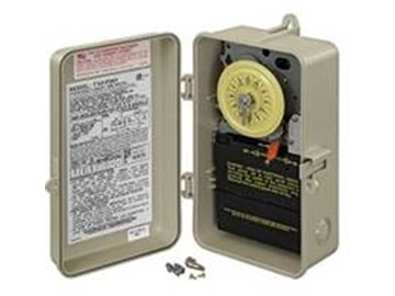
Running pool equipment 24 hours is usually unnecessary and expensive. Installing an Intermatic T104 timer is a great way to dramatically reduce run time and energy costs. The following steps will provide a guide on how to install the T104 timer. Note, timers vary with supply voltage. A T104 timer is used for 230V supply voltage. If you are using 115V supply voltage, you will need a T101 timer. The installation steps are the same for either.
Click Here to Find Your New Intermatic T104 Pool Timer 


Kevin Posted: 3/2/2023
When the timer clicks off the power it turns the clock off as well. How do I keep the clock running when the pump is off?Reply
InyoPools Product Specialist Matt S. Posted: 3/3/2023
Are you referring to the clock on a variable speed motor's mounted timer or the actual clock on the timer itself?Reply
JeaniB Posted: 4/21/2022
I just purchased a T104r to replace my timer after an unfortunate fire. My plan was to run my 1.5hp pump and my circupool rj 45 SWG. I have been running all at 110V,.. can I still do that with the T104r?Reply
InyoPools Product Specialist Matt S. Posted: 4/22/2022
We mention in the beginning, but T104 timers are for 220V, and T101 timers are 110V. You'll need to require your pump motor and salt system to accept 220 voltage if you want to use a T104.Reply
Anonymous Posted: 4/17/2022
If I want to run a pump and a salt generator would I hook both of them up to the 2 and 4 screws? I have a 104tr3Reply
InyoPools Product Specialist Matt S. Posted: 4/18/2022
Do you mean the T104R3 timer?Reply
Giles Posted: 10/10/2021
Can I run a 35A Heat pump AND an 11A pump on a single T104R?Reply
InyoPools Product Specialist Matt S. Posted: 10/11/2021
The T104 is only rated for 40A; your 46A load is too high.Reply
Kenneth Dinsmore Posted: 9/14/2020
It looks like my intermatic T101M is wired with 208. Can this be? Thanks for your help.Reply
InyoPools Product Specialist Matt S. Posted: 9/23/2020
A T101 mechanism is 120 volt only. The T104 is the 240 version.Reply
Eugene Posted: 5/3/2020
Where can I get a replacement door for a intermatic t104p timer?Reply
InyoPools Product Specialist Matt S. Posted: 10/27/2020
It looks like the door is not sold by itself but only available with a replacement enclosure. Metal Time Clock Enclosure Only / Plastic Time Clock Enclosure OnlyReply
Dave Posted: 3/10/2020
What is a good digital replacement for T104P time switch? I would like to have remote access to the digital time switch to enable on/off operation. Thank you for your recommendations.Reply
InyoPools Product Specialist Matt S. Posted: 3/11/2020
Hello, The digital replacement mechanism for the T104 is part number P1353MEReply
Jesse Anderson Posted: 2/14/2020
How do you install a second set of trippers to have it turn on and off again later in the day?Reply
InyoPools Product Specialist Matt S. Posted: 2/17/2020
Another set of trippers can be added to the clock face: Two Intermatic Trippers 1 Off & 1 On - 156T1978AReply
David Tank Posted: 12/21/2019
My instamatic timer has worked flawlessly for years now it turns on okay but turns off before it's supposed toReply
InyoPools Product Specialist Robert M. Posted: 1/3/2020
Is the "off" tripper still in the original position? It's possible it was inadvertently moved, causing it to kick off at the incorrect time.Reply
Jim Edwards Posted: 7/25/2019
On my box the wire pop outs are solid and there's no way to get them out, it almost looks like I'll literally have to drill them out with a small hole saw..is that normal? Shouldn't they be just pry out?Reply
InyoPools Product Specialist Matt S. Posted: 8/7/2019
The pop-outs should be relatively easy to remove, as they should just "pop out."Reply
John Pron Posted: 2/7/2019
My T104 is not turning on the equipment with the green pointer. The yellow wheel do not spin? The black gear through the large hole is spinning. The timer is advancing and will shut off the equipment with the copper turn off pointer. The manual lever is not going to the right to turn on my pool pump/ salt system. please assist. I have done all the steps as described in this guide. thanks johnReply
InyoPools Product Specialist Robert M. Posted: 2/8/2019
Hello John - You may have a defective mechanism. The replacement is part number T104M.Reply
John Pron Posted: 2/8/2019
i replaced the green arrow and torqed it down nice n tite. had extras. works real good now. The yellow wheel was indeed spinning nice and slow. Thanks all is good now. I have t104 in metal and plastic. `Peace.Reply
Kevin Posted: 6/25/2018
Thanks for these directions. They're excellent - clear, concise. I used them this afternoon, and we're back in business.Reply
Inyopools Posted: 4/9/2018
Hello Jim - We would suggest returning the T104 and getting the 110v T101 mechanism.Reply
Jim Posted: 4/6/2018
My GE 15307 timer clock quit working. The GE is discontinued so I bought an Intermatic 104 to replace. When I took the GE out I found I only had 110V going to the timer. When I put the Intermatic in it would not work. I put the old GE back in and the pump did work again but the timer clock did notReply
Inyopools Posted: 2/9/2018
carol - The T104 runs on 220V. Make sure your supply voltage to the timer is 220V. Check that the input voltage lines are connected to terminals 1 and 3 as shown in Step #14. Check that the white timer motor lines are also connected to terminals 1 and 3. Lastly, check that the yellow clock disc is engaged. Pull it out and release it a couple of time to make sure it engages with the timer motor gears.Reply
carol Posted: 2/3/2018
Just replaced a non functioning old Intermatic timer with same model T104. Checked that all is wired according to direction here. Turned back on and pool motor working fine but clock is NOT advancing. . . .!!Reply
Inyopools Posted: 11/26/2017
RP - Unfortunately, Intermatic timers are designed to control 220V or 115V. As far as I know, there is no way to rewire them to control both levels of voltage.Reply
RP Posted: 11/26/2017
I have a 220v intermatic timer controlling my pump. How can I hook up a 110v item or plug to it? Can I just use one of the 110v legs coming into the box, but where would my neutral wire go? Obviously the ground wire goes to the ground.Reply
InyoPools Product Specialist Dennis R. Posted: 9/28/2017
hello - Not that I am aware of. This is a 220V timer. Both of your supply wires are 110V and there is no neutral wire. The timer/clock is only set up to control 220V.Reply
hello Posted: 9/26/2017
I have 220 wired into the box. I'm running out teo outlets with 220. Is it possible to wire an additional outlet for 110? Thank youReply
InyoPools Product Specialist Dennis R. Posted: 8/30/2017
Anonymous (T104 trippers) - No, it does not matter where the manual switch is set. When the yellow dial rotates, the ON tripper will contact the switch at the time you set and flip it to ON (or leave it at ON). When the dial rotates to your OFF position, the OFF tripper will flip the switch to OFF. Make sure you have both trippers installed and that one is an ON tripper and the other is an OFF tripper. One is longer than the other.Reply
Anonymous Posted: 8/29/2017
You have a t104 are does it matter what the manual switch is set to will it still turn on and off if the timer is set to run at 10 a.m. and shut off at 3 p.m should it be in the off position all the time for the on position all the time would be leaving for several months but we wanted to run everyday and it doesn't seem to be doing that thank you.Reply
InyoPools Product Specialist Dennis R. Posted: 8/5/2017
Frustrated - I assume you replaced the whole timer and not just the motor or the timer mechanism. Check that you have the correct timer for your voltage. T104 for 220V. T101 for 115V. Then check that the white motor wires are connected to terminals 1 and 3. Also, check that the two supply wires from the breaker box are attached to terminals 1 and 3 and that the grounding wire from the box is attached to the grounding lug on the timer. Turn the manual timer switch off. Take the "ON" and "OFF" trippers off the dial so they aren't a factor. The motor should run and the yellow dial should advance in time.Reply
Frustrated Posted: 8/2/2017
My pool timer was 17 years old. I just had my pool resurfaced and shortly afterwards the timer quit working. If you looked into the peep hole you could see the gears turning but the clock dial didn't move (it was engaged, checked that). I purchased a new timer, installed it and the gears didn't even turn. Returned that one installed another new one. This one I could see the gears turning so I walked away to give the clock dial time to move. I came back later to find the breaker tripped at the box and also tripped the breaker at the main panel in the house. I reset the breakers and now the gears are no longer turning. What now?Reply
InyoPools Product Specialist Dennis R. Posted: 7/7/2017
Anonymous (timer ground) - If your timer doesn't have a ground wire coming into it from the breaker box, you should rewire that circuit to include a ground wire.Reply
Anonymous Posted: 7/4/2017
Trying to replace a timer, but there was no ground wire on the one being replaced. What's a solution?Reply
InyoPools Product Specialist Dennis R. Posted: 7/4/2017
Stephen - Thank you for your feedback. You are correct. 12 gauge wire could not be used on a heater's 60 amp circuit. It would be more like 6 gauge. However, this timer installation is intended for a pump, not a heater. I do not see where we say that a 12 gauge wire is required to connect the timer to a heater. We could probably be clearer on how this timer is going to be used.Reply
Stephen Posted: 6/30/2017
It shows that 12 gauge wire is used to connect the timer to the heater. How can that be when at 60 amps that wire would not suffice? I'm confused. I have a 125 BTU Hayward heat pump and was told to use an Intermatic Timer 220 Volt Plastic Enclosure - T104P3. Does anyone have the same combo? If so, how did you wire it?Thanks
Reply