5 out of
5 stars on
1
ratings
(Click on a star to add your rating)
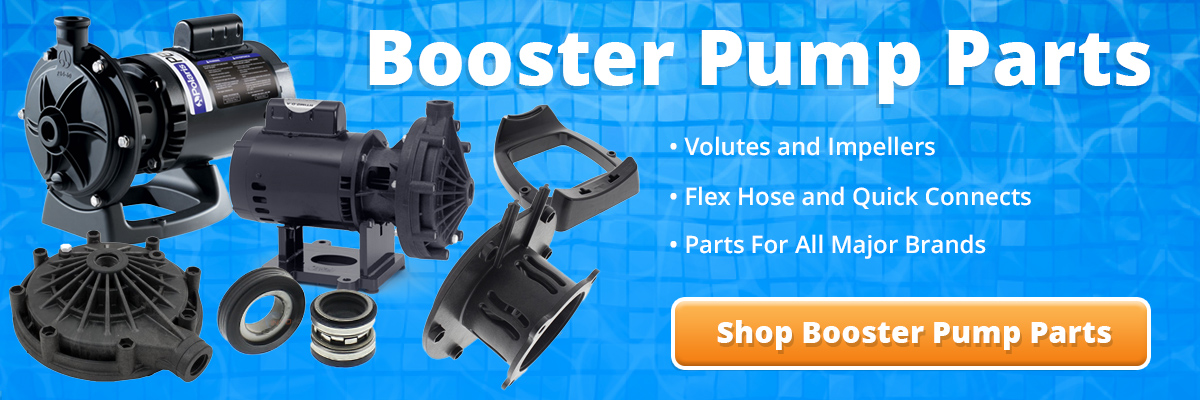
This guide provides a step by step procedure for replacing a motor on a Polaris Booster Pump. Although it features a Polaris Booster pump from 2011 to present, similar steps can be applied to all variations.
Here's a list of common tools you will need to replace your motor: screwdrivers (Phillip head and flat), 9/16" socket wrench, 7/16" open end wrench, channel wrench or strap wrench, silicon gasket lubrication (do not use petroleum jelly), clean soft cloth, "GO KIT" - pool pump seal replacements.
Step 2
TURN OFF POWER - Before you start, make sure that the power to the pump is turned OFF. For maximum safety turn off the power at the circuit breaker to the motor.
Step 3
Disconnect the hoses from the fittings on the volute.
Step 4
Disconnect the bonding wire from the back of the motor.
Note: We had to cut this one off because the bonding lug was corroded. You may not need to if you can loosen the screw on the bonding lug.
Step 5
Remove the back panel on the motor in order to gain access to the wires.
We used a 1/4" socket to remove the bolts.
Step 6
Disconnect the three wires that are coming in through the conduit.
Step 7
Unscrew the conduit adapter and pull out the conduit and wires from the motor.
Step 8
Move the motor to a location where it is easy to work on.
Step 9
Remove the 6 bolts located on the front of the volute. We used a 1/2" socket to remove the bolts.
Step 10
The next steps will involve removing the impeller. First, remove the cap that covers the shaft of the motor.
Step 11
Stabilize the shaft. We used a 1/2" wrench.
Step 12
While stabilizing the shaft from the back of the motor, spin the impeller off counterclockwise.
Step 13
Remove the 4 bolts that secure the bracket to the motor. We used a 9/16" socket.
Step 14
Remove the bracket from the motor.
Step 15
Separate the bracket from the base by pressing the tabs on the underside of the base.
Step 16
The next steps will involve removing and replacing the shaft seal. First, remove the spring portion of the shaft seal from the impeller.
Step 17
Remove the white ceramic seal from the bracket. That should include the black rubber ring that goes around the ceramic portion.
Step 17
Take the new white ceramic portion of the shaft seal and press it into the bracket. The white ceramic side should be facing out.
Note: Use a clean cloth to press the seal in place. You don't want to get fingerprints on the ceramic.
Step 18
Press the spring portion of the new seal onto the shaft of the impeller. The rubber side of the spring portion should face the impeller. The shiny side will need to face out so that it will end up facing the white ceramic portion that was pressed into the bracket.
Step 19
Press the bracket back onto the pump base.
Step 21
Slide the new motor onto the base and feed the shaft through the bracket.
Step 22
Secure the motor to the bracket using the 4 bolts from Step 13. Tighten with 9/16" socket.
Step 23
The next step will involve reinstalling the impeller. Remove the black cap on the back in order to gain access to the shaft.
Step 24
Using a 1/2" wrench, stabilize the shaft at the back of the motor and spin the impeller on clockwise. Do not overtighten. Just firm enough to move the wrench.
Step 25
Install the bracket o-ring. We recommend lubricating it with a silicone or teflon lubricant.
Step 26
Reinstall the volute onto the bracket and tighten the 6 bolts from Step 9.
Step 27
Get the pump fittings and wrap teflon tape around the threads.
Step 28
Thread the fittings onto the discharge and intake of the pump.
Step 29
Move the pump back into the original location and remove the plate on the back that covers the terminal board.
You can also thread the conduit adapter into the threaded hole next to the terminal.
Step 30
The motor comes from the factory set on 230V (high voltage) and that is how we wired this motor. There is a 115V (low voltage) wiring diagram on the motor label if that is how you need to wire the motor.
Step 31
Feed the wires through the conduit adapter. Connect one "hot" line to terminal 1 and the other to terminal 6. Connect the green ground line to the green ground screw.
Note: The "hot" lines in most applications are black and red. It doesn't matter which color goes to each terminal as long as one goes to terminal 1 and the other to 6.
Step 32
Place the terminal cover over the terminal and tighten the screws.
Step 33
Reconnect the bonding wire to the bonding lug on the back of the motor.
Step 34
Press the hoses onto the fittings. Make sure the intake and return hoses are connected to the correct ports. The intake is at the front of the pump and the discharge is on top.
Step 35
Tighten the nuts down to secure the hose to the fittings.
Step 36
The pump is now completely installed and you can turn the power back on.


Be the first to add a comment