How to Set the Cams on an Intermatic Pool Valve Actuator

WRITTEN BY: 

  3 out of 5 stars on 4 ratings
(Click on a star to add your rating)

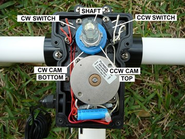
The Intermatic Valve Actuator can be mounted on top of a 3-way valve in four different positions relative to the 3 ports of the valve. If the Actuator is mounted in the standard, most common, position, the Actuator Cams do not have to be changed. If the Actuator is mounted in any of the other three positions, the Cams of the Actuator will have to be reset. This guide identifies the location of the Cams and shows how to adjust them.

Step by Step

Top

Step 1

FOUR MOUNTING OPTIONS - The Intermatic Valve Actuator can be mounted on top of most diverter valve products in any of the four mounting options shown here. Depending on how the water flows into and from the three ports, you may have to change the cams within the Actuator to change the control of flow through the ports.

Step 2

CAM SETTING TABLE - This table is used to determine the Cam settings for any of the four Actuator mountings. As you can see the Cam settings are based on both the Actuator mounting and the direction of water flow through the Valve. The "Open" port on the Valve is always open and the two "Controlled" ports are open or shut depending on the Actuator operation. The Actuator can be mounted in 4 different positions and each position has three water flow options. For example, let's look at the most common installation for an Actuator "A2" on the chart - MOUNT A with OPEN PORT 2. Water enters or exits port 2 and flows in or out of ports 1 and 3. In this installation water always flows through port 2 and is controlled at ports 1 and 3. For this installation and in accordance with this Table, both the bottom cam and the top cam will be set at 0. However, it is unclear where the handle is pointing when you set change these Cam settings. So we are suggesting that you use the following procedures to set your Cams until we can get further clarification on how to interpret the Table.

Step 3

MOUNTING ACTUATOR - For instruction on mounting this Actuator, see our guide on "How To Install a Pool Valve Actuator".

Step 4

SETTING CAMS - The balance of this guide provides a couple of actual examples for setting the cams: two for Mounting A - including the Standard position; and two for Mounting B.

Step 5

TURN POWER OFF - Turn off the power to the pump.

Step 6

TURN ACTUATOR OFF - Flip the toggle switch located on the back end of the Actuator to "OFF".

Step 7

CHECK ACTUATOR POWER - Make sure that the Actuator is connected to the Control Box for power.

Step 8

SET UP FOR MOUNT A - This is the set up position for Mount A as shown in the Step 1 above. Mount A has three different Cam settings depending on your piping configuration. We will first show you how to set up for the most common (standard) Cam setting - This is how the Actuator is shipped from the manufacturer. Piping for the standard position is discussed below.

Step 9

REVIEW WATER FLOW FOR OPTION A2 (STANDARD) DISCHARGE - Note the flow of the water through the valve. For this option the water must flow into the center port and out either or both of the end ports. The center port will always be open. Either of the end ports can be shut off with the valve. This is the configuration for a diverter valve after the pump. An example of this use is water flowing from the filter to the pool or the spa or both.

Step 10

REVIEW WATER FLOW FOR OPTION A2 (STANDARD) SUCTION - When configuring this Actuator/valve for an A2 setting on the suction side of the pump, the water flow will be reversed. Water will come from either or both ends and will exit out the center port. An example of this use is water coming from the pool drain or the skimmer or both, and exiting to the pump. In either setup, discharge or suction, the cam setup will be A2. The common criterion for both setups is that the A2 the center port is always open regardless of which way the water flows in it. Only the end ports can be closed off (controlled).

Step 11

REMOVE LOCKING KNOB - Unscrew the Valve Locking Knob off the top off the Actuator.

Step 12

REMOVE VALVE HANDLE - Lift off the Valve Handle and set it aside. It will be replaced shortly.

Step 13

REMOVE COVER SCREWS - Remove the 4 screws that secure the Actuator cover.

Step 14

REMOVE COVER - Lift the cover off the top of the Actuator.

Step 15

REPLACE THE HANDLE - Replace the Handle on the open shaft to show how the shaft is rotating when commanded. Note that one of the slots in the Valve stem is smaller that the other three. The small slot of the Valve stem must line up with the small tooth in the Handle.

Step 16

TOGGLE ON/OFF SWITCH - Flip the toggle switch located on the back end of the Actuator from "OFF" to "ON2".

Step 17

ROTATE HANDLE TO PORT 1 - "ON2" will cause the Handle on the Actuator to rotate counter-clockwise (CCW). If the Cams are set at the factory defaults, the Handle will stop at the point where the Valve completely shuts off the water through Port 1.

Step 18

CHECK CAM SETTINGS - With the Valve rotated fully CCW over Port 1, the top Cam should be positioned so that the "0°" mark on the top Cam lines up with the arrow on the right switch housing. At this setting the "0" on the bottom Cam should also be lined up with the arrow on the left switch housing. Since these are the factory default settings, the Cam should not have to be reset. If they aren't set to "0" or if the Handle didn't stop at the correct position, the Cams will have to be adjusted as will be explained a little later.

Step 19

ROTATE HANDLE CW - Flip the toggle switch located on the back end of the Actuator from "ON2" to "ON1". This should cause the Handle on the Actuator to rotate clockwise (CW) 180° until the Valve completely shuts off the water through Port 3

Step 20

CHECK CAM SETTINGS - With the Valve set to shut off Port 3, the top Cam should be positioned so that the "180°" mark on the Cam lines up with the arrow on the right switch housing. Also, the "180" on the bottom Cam should also be lined up with the arrow on the left switch housing. If you are installing this Actuator in an A2 configuration, you do not need to continue through the next three examples. Skip to Step 42.

Step 21

SET TOGGLE SWITCH TO "OFF" - Flip the toggle switch to the "OFF" position to set up for the next Cam setting option.

Step 22

SET UP FOR OPTION A1 - The standard position described above will be used in the vast majority of Actuator installations. However you may run into special plumbing cases where you will have to install the Actuator in a different configuration that will require the Cam to be changed from the factory default. Three of the 12 possible configurations shown in Cam Setting Table are addressed next: A1, B1 and B2.

Step 23

°REVIEW WATER FLOW FOR OPTION A1 - This option assumes that the Actuator is still installed in Mount A position but the water flow through the valve has changed. For discharge, water is flowing into port 1 and flowing out either port 2 or port 3 or both. Port 1 will always be open. Port 3 can be shut off with a CCW rotation, and port 2 with a CW rotation.

Step 24

MANUALLY ROTATE CW - The Valve is current configured to stop at Port 3 when power rotated CW. The CW switch is open and will not advance past Port 3. Manually rotate the valve CW by pushing down on the Valve Shaft and twisting it CW. A 10-15° rotate is sufficient - just enough to get the Cam nub off the left switch.

Step 25

POWER ROTATE HANDLE CW - To initiate a Port 2 closure, flip the toggle switch from "OFF" to "ON1". This should start the Handle on the Actuator to rotate clockwise (CW).


Step 26

STOP HANDLE AT PORT 2 - When the Handle is positioned so that it is completely shutting off port 2, flip the toggle switch to "OFF". Next, prepare to set the bottom Cam so that the Actuator will automatically stops at this position with a programmed CW command.

Step 27

REMOVE VALVE HANDLE - Lift off the Valve Handle.

Step 28

REMOVE LOCKING NUT - The Locking Nut secures the two Cams to the bottom of the Valve Shaft. Remove the Nut by screwing it CCW and lifting it off the Shaft.

Step 29

REMOVE SPACER - There is a Spacer Ring under the Locking Ring. Lift the Ring off of the Shaft.

Step 30

REMOVE TOP CAM - Remove the top Cam by lifting it off the Valve Shaft.

Step 31

LIFT BOTTOM CAM - There is an O-ring just above the bottom Cam that holds the bottom Cam down. You may have to lift the bottom Cam slightly to bring the O-ring up just enough to rotate the bottom Cam.

Step 32

SET BOTTOM CAM - The bottom Cam controls the CW rotation. Rotate the bottom Cam so that the nub of the bottom Cam closes the left switch (opens the circuits and stop motor and CW rotation).


Step 33

REPLACE TOP CAM - Place the top Cam back onto the Valve Shaft and press down to reset the O-ring.

Step 34

ROTATE HANDLE CCW - Flip the toggle switch from ""ON1"" to "ON2". This should cause the Handle on the Actuator to start to rotate counter-clockwise (CCW).

Step 35

STOP HANDLE AT PORT 3 - When the Handle is positioned so that the Valve is completely shutting off port 3, flip the toggle switch to "OFF". We will now set the top Cam so that the Actuator automatically stops at this position on a programmed CCW rotation command.

Step 36

SET TOP CAM - The top Cam controls the CCW rotation. Rotate the top Cam so that the nub of the bottom Cam closes the right switch. The 0° mark on the top Cam should now line up with the arrow on the right switch. The 270° mark on the bottom Cam should line up with the arrow on the left switch. Note: These settings are not consistent with the Cam Setting Table, but they are correct for where the Handle is pointing now.

Step 37

REPLACE SPACER AND LOCKING NUT - After you have set each of the Cams, replace the Spacer Ring and screw the Locking Nut CW onto the Valve Shaft. Hand tighten.

Step 38

SET UP FOR OPTION B1 - The next series of steps shows how to set up the Cams for option B1. The Actuator is mounted 90° CW from how it was mounted in Mounting A and the open port is Port 1.

Step 39

VIEW FOR MOUNTING B - For our second set of examples, we will install the Actuator in Mount B position as shown. The body of the Actuator is lined up with the pipe coming into port 1.

Step 40

REVIEW WATER FLOW FOR OPTION B1 - For a B1 setup up (discharge), the water will flow into port 1 and be discharged into port 2 or port 3 or both.

Step 41

SET CAMS FOR B1 - Use the same procedures as provided above for A1 to set the Cams for this option. Rotate CW to shut off port 2. Set bottom Cam. Then rotate CCW to shut off port 3. Set Cam. The Cam settings after CCW setting should be at: Top Cam - 90°; Bottom Cam 180°.

Step 42

SET UP FOR OPTION B2 - The next series of steps shows how to set up the Cams for option B2. The Actuator is mounted the same as B1 but the open port is now Port 2.

Step 43

REVIEW WATER FLOW FOR OPTION B2 - For a B2 setup up (discharge), the water will flow into port 2 and be discharged into port 1 or port 3 or both. You will note that the water flow is the same as for A2. The cams have to set differently because the actuator as mounted was rotated 90° from the Mount A position. The control of water flow through the valve is the same for both A2 and B2 (and C2 and D2 for that matter).

Step 44

SET CAMS FOR B2 - Use the same procedures as provided above for A1 to set the Cams for this option. Rotate CW to shut off port 3. Set bottom Cam. Then rotate CCW to shut off port 1. Set top Cam. The Cam setting after the CCW setting should be at: Top Cam - 90°; Bottom Cam 270°.

Step 45

CLOSE UP ACTUATOR - After you have set the Cams in the Actuator for any of the 4 options discussed above, you will close the Actuator.

Step 46

REPLACE AND SECURE COVER - Replace the actuator cover and secure it with the 4 screws.

Step 47

REPLACE HANDLE - Align the handle tabs with the slots in the actuator shaft and slide the handle onto the shaft.

Step 48

REPLACE LOCKING KNOB - Screw the Locking Knob on top of the Handle.

Step 49

TURN ACTUATOR ON - Flip the toggle switch on the backside of the Actuator to one of the "ON" positions. See our guide on "How to Sync Pool Valve Actuators" if you have more than one Actuator that operate together.

Comments

Top

Be the first to add a comment