How To Install a 2-Speed Motor and a T106 Timer

WRITTEN BY: 

  2.96 out of 5 stars on 23 ratings
(Click on a star to add your rating)

With the cost of electricity continuing to increase, it is a good idea to replace a single-speed motor with a more energy-efficient 2-speed motor. This guide will explain how to install a 2-speed motor as well as add an Intermatic T-106 timer to control the high and low speeds. Although this guide is specific to replacing a Sta-Rite Dura-Glas motor, most of the steps can be applied to other models of pumps.

Step by Step

Top

Step 1

Make sure that the power to the pump and timer is turned OFF. For maximum safety turn off the power off at the circuit breaker.

Step 2

The first steps will involve installing the T106 timer next to an existing T104 timer.

Click here to view the T106 timer. 

Step 3

Locate an area on the wall near the existing timer for the T106. Locate the timer out of reach of the sprinklers or drainage spouts.

Step 4

Mark the locations for the three mounting screws. One is located on top of the timer box and two are located inside the timer box towards the bottom.

Step 5

Drill three holes where the mounting screws will be installed. Note: We used a special 3/16" carbide drill bit to drill into the concrete.

Step 6

Install screws (or other hardware appropriate for the mounting surface) through the mounting holes of the Intermatic T106 timer box. Note: We used 1/4" x 1-1/4" hex head, concrete anchors. Hex head anchors are recommended for better traction when installing into the concrete.

Click here to view the T106 timer. 

Step 7

Remove two of the knockouts from the timer box. One knockout will lead to the existing T104 timer and the other will lead to the pool pump.

Step 8

Thread two conduit adapters into the Intermatic T106 timer.

Step 9

At this point the T106 is installed onto the wall. We will now replace the motor on the pool pump. After the motor is installed we will return to the timers to complete the wiring part of the  installation.

Step 10

The next steps will involve removing the old motor from the pump and installing the new 2-speed motor.

Click here to view Sta-Rite Duraglass 2 speed motors. 

Step 11

The first step in removing the motor from the Sta-Rite Dura-Glas pump is to loosen the clamp knob and remove the metal clamp.

Step 12

Once the clamp is removed, slide the motor back and away from the front part of the pump.

Step 13

Unfasten the external ground cable from the boding lug located on top of the motor.

Step 14

With a 1/4" socket, remove the two screws from the back of the motor cap.

Click here to view Sta-Rite Duraglass parts. 

Step 15

Remove the end cap and disconnect the three cables coming into the motor from the conduit.

Step 16

The motor is now completely disconneccted and can be lifted out to be worked on in a more convenient area.

Step 17

Locate the diffuser at the front of the pump and remove the five screws. After the screws are removed, pull off the diffuser.

Step 18

In order to remove the impeller, the shaft of the motor will need to be stabilized.

Click here to view Sta-Rite Duraglass parts. 

Step 19

In order to stabilize the shaft, the thermal protector will need to be removed from the back of the motor. Unscrew the single screw that holds the thermal protector in place. There is no need to remove the thermal protector from the leads.

Step 20

Place a 7/16" wrench on the flat side of the motor shaft to secure the shaft from rotating.

Step 21

While holding the wrench at the back of the motor, spin the impeller off counterclockwise. A strap wrench may be needed if the impeller cannot be removed by hand.

Click here to view the rubber strap wrench. 

Step 22

The next step will be to reomve the seal plate.

Step 23

The four bolts will need to be removed that connect the motor to the seal plate. The bolts can be removed by using a 9/16" socket.

Step 24

With the four bolts removed, pull the seal plate off of the motor.

Step 25

Take the old shaft seal out of the seal plate. The shaft seal is a two-part seal. The first piece is a spring and the second piece is a white ceramic part which is pressed into the seal plate.

Click here to view Sta-Rite Duraglass parts. 

Step 26

The next steps will involve installing the new motor onto the existing Sta-Rite Dura-Glas pump. Every part will be reused from the old pump except for the new shaft seal and o-rings. All o-rings and shaft seals should be replaced whenever a new motor is installed.

Step 27

Find the new white ceramic piece of the shaft seal. Press it into the seal plate with the white side facing out. Gently wipe the polished face of the ceramic seal with a soft clean cotton cloth. There should be no fingerprints on the ceramic piece.

Step 28

Slip the seal plate onto the motor. Then place the motor and seal plate onto the motor base.

Step 29

Attach the motor to the seal plate with the four existing motor bolts. Use a 9/16" socket to tighten the bolts. Note: Make sure you feed the two longer bolts through the motor base and then into the seal plate. The seal plate will be damaged if the two longer bolts are installed without the motor base in place.

Click here to view Sta-Rite Duraglass parts. 

Step 30

Locate the spring part of the shaft seal. Press the spring portion onto the shaft of the motor. The shiny black side of the spring portion should be touching the white ceramic piece.

Step 31

Unscrew the two screws that hold the cover over the back end of the motor. Remove the cover to expose the electrical connectors.

Step 32

To reinstall the impeller, place a 7/16" wrench on the flat side of the motor shaft to secure the shaft from rotating.

Step 33

Screw the impeller on clockwise while holding the back of the motor shaft with a wrench. The impeller does not need to be overtightened.

Click here to view Sta-Rite Duraglass parts. 

Step 34

Lubricate the diffuser o-ring with silicone or teflon lubricant and reinstall the o-ring on the diffuser.

Click here to view the Magic Lube O-ring Lubricant. 

Step 35

Place diffuser onto the seal plate and tighten the 5 screws.

Step 36

Thread a 1/2" conduit adapter into the hole near the back of the motor.

Step 37

The next steps will involve connecting the cables to the new motor.

Step 38

A 2-speed motor requires what is called a three-wire cable. There are actually four wires within the cable; two hot wires, one common wire, and the ground wire. For this installation, we used a 14-3 cable. Make sure there is enough cable to run from the pump to the furthest timer.

Click here to view Sta-Rite Duraglass parts. 

Step 39

Note: It is easier to connect the wires to the motor before the motor is connected to the pump.

Step 40

Locate the terminal board at the back of the motor. This will be labeled for the correct location of the wires. L2 is the common, L1 is the high speed, A is the low speed, and the green screw is the ground.

Step 41

With a wire stripper, strip away approximately 1/2"-3/4" of the colored insulation from the red, black, and white wires.

Step 42

Feed all four wires through the conduit adapter that was threaded into the motor.

Click here to view Sta-Rite Duraglass parts. 

Step 43

Connect the black wire to "L1" terminal. This will be the "hi speed" line. Connect the white wire to to the "L2" terminal. This will be the "common" line. Connect the red wire to the "A" terminal. This will be the "low speed" line. Finally, connect the exposed copper or green line to the green screw. This is the "ground" line.

Step 44

Place the black end cap back on the motor and tighten the screws.

Step 45

At this point, the motor assembly can be reinstalled onto the rest of the pump. Put the black end cap back on the motor and slide the motor assembly into place and connect the metal clamp.

Step 46

Measure the distance from the 2-speed motor to the T106 timer. Cut a piece of 1/2" electrical conduit to the correct distance.

Click here to view Sta-Rite Duraglass parts. 

Step 47

Feed the cable from the 2-speed motor through the 1/2" conduit. Push the one end of the conduit into the conduit adapter on the motor. Note: We recommend using a little bit of dish soap to lubricate the cable. This will make it much easier to feed it through the conduit.

Step 48

The next steps will involve wiring the pump to the timers and the T106 to the T104.

Click here to view the T106 timer. 

Click here to view the T104 timer. 

Step 49

A jumper will need to be installed in order to connect terminals 1 and 4 in the T106 timer. A jumper is basically a small cable that connects the terminals. You can use a small piece of cable from the 14-3 cable. It does not matter what color. Strip a 1/2" from either end. Connect one end to terminal 1 and the other to terminal 4. This is displayed in the picture with a red cable.

Step 50

In this step you will need to measure and cut another jumper. This jumper will have to be long enough to run from terminal 1 in the T106 timer to terminal 2 in the T104 timer. This will be diplayed in the picture by a red cable running underneath the first jumper. At this point, one end of the jumper can be connected to terminal 1 in the T106 timer. In a later step we will feed this jumper through a conduit to terminal 2 in the T104 timer.

Step 51

The next cables to be measured and cut will be the cables that connect the motor from the T106 to terminals 1 and 3 on the T104 timer. Remove the T106 white motor cables terminals A and 3. Remove the metal ends from the motor cables. Measure and cut 2 cables long enough to reach from the T106 timer to terminals 1 and 3 in the T104 timer. Using wire nuts,  connect one cable to each of the motor cables. Eventually these lines will be fed through a conduit to the T104 timer. The motor cables are represented with green lines in the picture.

Step 52

Feed the cables running from the pool motor and feed them through the conduit adapter and into the T106 timer.

Click here to view Sta-Rite Duraglass parts. 

Step 53

Strip 1/2" of the colored insulation off the black wire and red wire that were just fed into the T106. Connect the black wire (hi speed) to terminal 3. Connect the red wire (low speed) to terminal 2.

Step 54

Loosen the green screw at the bottom of the T106 timer. Loop the green ground wire around the screw and tighten the screw. Make sure that the piece of ground wire that loops the ground screw has been stripped so the copper is exposed. This same ground line will be fed through the conduit to the T104 timer in the next few steps. This will ground the pump, T106, and T104 together.

Step 55

Feed the white common line from the pump, the second jumper, the 2 timer motor wire leads, and the ground line through conduit to the T104 timer.

Step 56

Connect the 2nd jumper line from terminal 1 in the T106 timer to terminal 2 in the T104 timer. Connect the T106 motor leads to terminals 1 and 3 in the T104 timer. Connect the white common line from the pump to terminal 4 in the T104 timer. Lastly, connect the green ground line to the ground screw inside the T104 timer box. The diagram will show what the completed connection should look like. Click on the image to enlarge.

Click here to view the T106 timer. 

Click here to view the T104 timer. 

Step 57

The T106 timer should now be successfully connected to the T104 timer. The T104 will now control the low speed when the T104 is in the ON position. We will now set the trippers on the both timers. This will control when the pump turns on and when it will switch to the high speed.

Step 58

The T104 timer should be set first. The T104 will control the low speed of the timer. We recommend running the low speed the majority of the day. You may use the low speed the entire day if you only require the high speed to manually vacuum the pool or backwash the filter.

Step 59

To set the T104 timer, the time will need to be selected. There is a silver Time Pointer on the Clock-Dial. This Time Pointer will point directly to the current time.

Step 60

To set the time, pull the Intermatic Clock-Dial outward. Turn the dial in either direction and align the exact time of day on the Clock-Dial to the Time Pointer. The picture displays the timer set to 12:00 pm.

Click here to view Sta-Rite Duraglass parts. 


Step 61

The next steps will demonstrate how to set the trippers. The trippers will determine when the equipment will turn on and off.

Click here to view the trippers. 

Step 62

Locate the "On" tripper. The "On" tripper is typically green and will be labeled "On".

Step 63

To set the "On" tripper, hold the tripper against the desired time and tighten the tripper screw firmly. The picture displays the "On" tripper set at 8:00 am.

Step 64

Locate the "Off" tripper. The "Off" tripper is typically gold and will be labeled "Off".

Step 65

To set the "Off" tripper, hold the tripper against the desired time and tighten the tripper screw firmly. The picture displays the "Off" tripper set at 4:00 pm.

Click here to view Sta-Rite Duraglass parts. 

Step 66

The Intermatic T104 Series Timer is now programmed. Next you will need to set the T106 timer. Again, The T106 will turn the high speed on and off. You will want to set the high speed to run while the T104 is on. Example: If the T104 turns the low speed on at 8am and off at 4pm, the T106 should be set to turn on at 12pm to 2pm (each pool is different so set the schedule to your preference). To set the T106 timer, repeat steps 59-65.

Step 67

Both timers should now be set. The power can now be turned back on at the breaker. The Intermatic T106 and the 2-speed motor have now been installed correctly. Enjoy the sunstantial energy savings of a 2-speed pump and timer.

Comments

Top
(1 to 17 of 17)

 Posted: 2/9/2019 

Where would my salt chlorinator tie in at? It’s suppose to run same time as pump but I’m not sure at low or high speed.
 Reply

InyoPools Product Specialist  Posted: 2/12/2019 

Hello Sparky - You would connect the salt system to the T104 timer or whatever timer turns the pump on & off. It should be connected to the "load" terminals. The salt system may be able to operate at both speeds. It will turn itself off if the flow is too low on the low speed.
 Reply

 Posted: 7/27/2018 

Yes, low speed is the money saving speed. High speed should only be needed for specific reasons. This would include backwashing the filter, vacuuming the pool, running spa jets and other water features.
 Reply

Anonymous  Posted: 7/23/2018 

Step 58 recommends low speed for majority if not all day,is this $ saving speed ?
 Reply

InyoPools Product Specialist  Posted: 8/14/2017 

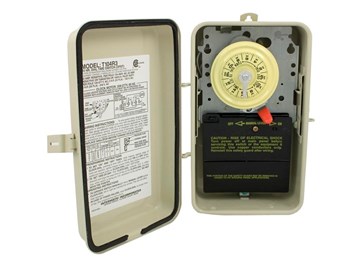
Sj70764 - This guide shows you how to add a T106 timer to an existing T104 timer to convert your single speed pump system to a two-speed pump system. There is another, more expensive, way to replace your T104 timer with a timer that handles a 2-speed pump. See our guide on "How To Set Up the Intermatic Pool-Spa Control System for 2-Speed Pump".
 Reply

 Posted: 8/11/2017 

Why do you have to have two timers. My 2 speed pump only has one timer
 Reply

InyoPools Product Specialist  Posted: 3/10/2017 

Jay Finke - Thank you for your response. We had our motor rep look at your comment. Here was his response:
"There isn’t any standard for color, and we don’t put anything in print about the wire colors for field wiring. It is common in practice to use black for high, and red for low. For most codes, if a white wire is part of a 230 volt circuit, a piece of black tape should be put around the wire which would possibly give a clue that it is hot. Of course, a service person would not know if a person who hooked it up actually followed the recommended procedure. The real answer is a “qualified” service person would confirm all the circuits before applying power. Applying power to both high and low speeds at the same time may damage the windings before the overload has time to react."

 Reply

 Posted: 3/9/2017 

please, (everybody) use red wire as low, black as high and white as common. it makes it easier on the Pool Pump Motor Repair Guy when it calls for service.
And hooking power up to high and low at the same time will SMOKE the motor in a matter of seconds, the motor will be damaged beyond repair.
Two-speed motors save power and usually outlast single speed motors, run on HIGH for 2 hrs and LOW the remainder around 8 hours total.

 Reply

 Posted: 4/6/2016 

Just use a pe103 timer and be done with it. Its a lot safer.
 Reply

InyoPools Product Specialist  Posted: 11/30/2015 

Simon Reilly - No. The timers are only gating power to the pump motor. The T104 timer turns the power on and off. The T106 timer, in series, switches the power to low speed or high speed when the power is on.
 Reply

 Posted: 11/29/2015 

Will the motor be destroyed if both timers are on at the same time?
 Reply

InyoPools Product Specialist  Posted: 9/11/2015 

T106 Timer - The way the timers are wired, timer (106) cannot be activated until the 104 timer is turned on. Timer 104’s only function is to provide power to 106. Timer 106 provides the switching function between Low and High speeds. When 104 is switched on, power flows through 104 to 106. If 106 is in the off position, power will flow through the Low speed circuit of the 106 timer to the pump. When the 106 timer is switched on, it will switch from the Low speed circuit to the High speed circuit within the 106 timer. When the 106 timer switches off, the 106 timer reverts back to the Low speed circuit. When the 104 timer is shut off, power to 106 is shut off which shuts off power to the pump.
 Reply

Anonymous  Posted: 9/9/2015 

What would happen when the High (106) is on but the Low (104) is off?
 Reply

Anonymous  Posted: 7/21/2015 

Thanks for documenting, and your willingness to share.. This helped me very much... Your awesome.
 Reply

Anonymous  Posted: 3/24/2015 

Thanks for clarifying. I appreciate the detailed steps for changing out my pump motor.
 Reply

InyoPools Product Specialist  Posted: 3/23/2015 

T106 wiring - Thank you for bringing this to our attention. You are correct. The last sentence in Step 53 should read "Connect the red wire (low speed) to terminal 2" to coincide in the picture?
 Reply

Anonymous  Posted: 3/22/2015 

Step 53 is written to connect red wire to terminal 4 yet the drawing shows it connecting to terminal 2 and drawings elsewhere also show the red wire from the pump motor connecting to the number 2 terminal in the T106 timer. Shall I follow the drawing or the text?
 Reply