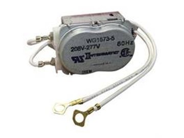
The clock motor in an Intermatic T104 Timer will occasionally fail. If the yellow wheel stops turning but the manual switch still functions correctly, It may be due to one of two failures, the timer motor or the timer mechanism. The following steps show you how to replace the motor, WG1573-10D. Note, this motor is for a T104 220V timer. If you have a 110V timer, T101, use motor WG1570-10D.
Please click here to view Intermatic Timers. 


Anonymous Posted: 5/23/2020
Thank you for the useful help!Reply
Rose ODonnell Posted: 6/29/2019
Perfect! Thank you!Reply
John kostanian Posted: 12/12/2018
You have explained very thing very well, you deserve a big bravo.Reply
InyoPools Product Specialist Dennis R. Posted: 10/4/2017
Anonymous (125V motor) - Unfortunately, a 125V timer motor will not work in your T104 timer. The T104 timer is wired to control a 220V output (pump) and its motor runs off that voltage.Reply
Anonymous Posted: 10/1/2017
Previous comment in order to get email response.Purchased Motor wg1570-5 125V, however the old motor says 220V. Would this work anyways?
Reply
AySz88 Posted: 6/23/2017
Not all T104 timers contain WG1573-10D motors; mine contained a WG433-3 motor (supposedly equivalent to a WG433-20D). The WG433 has a slightly larger gear, and gets positioned through a different hole on the timer's backplate.Reply
InyoPools Product Specialist Dennis R. Posted: 6/13/2017
J. Johnson - It's not clear what you had replaced in your timer. If you replaced the timer mechanism, you should have solved any problems with the auto on/off not working. It's like having a new timer. See our guide on "How to Replace an Intermatic T104 Mechanism".Reply
J. Johnson Posted: 6/11/2017
I recently had a company come and service my timer, because the pump would not turn on/off automatically. I had the old timer and motor replaced, but the auto on/off is still not working. Any suggestions?Reply
InyoPools Product Specialist Dennis R. Posted: 5/22/2017
Anonymous (T104) - Sometimes with older timers, the gears get sloppy and will bind during operation, even when the spin freely off the motor. I would try replacing the timer mechanism. Here is the link to the Intermatic Timer Mechanism Only 220V.Reply
Anonymous Posted: 5/20/2017
My clock was not turning but the manual switch worked so I replaced the motor, however the clock is still not turning. There is power to the motor. With the motor removed the gears in the box spin freely. Any suggestions?Reply
InyoPools Product Specialist Dennis R. Posted: 5/2/2017
Greg G - It sounds like your need to replace T104 Mechanism. Here's a link to our guide on "How to Replace an Intermatic T104 Mechanism".Reply
Greg G Posted: 4/30/2017
My Intermatic T104 Timer is not running and the pump does not come on when I switch it on manually. Does this mean I am not getting power to the timer altogether or does the manual switch become nonfunctional if the timer blow is out?Reply
InyoPools Product Specialist Dennis R. Posted: 8/29/2016
cerylus - It is unlikely that your new timer is bad. T104 is a 220V timer. Make sure that you have 220V going to your timer and not 110V. Check that your supply lines are going to timer terminals 1 and 3 and the ground wire is attached to the ground lug. Then, remove the timer mechanism to access the motor. Take the motor off the back and run the timer with all the wires connected to make sure the motor is running. Be careful with the exposed connections. They have 220V on them. Replace the motor and confirm that the mechanism gears are turning and are not jammed.Reply
cerylus Posted: 8/27/2016
Thanks for providing great guides. In my case, I replaced our pool timer with a new one (T104M 24Hr Mechanical Time Switch) because it was turning on/off (the timer was not turning). With the new replacement, it's still doing the same thing, the timer is still not turning. :-( Did I replace it with another broken one? Can you help how to check where it's broken or what needs replacing? I'd appreciate your help. Thanks.Reply
InyoPools Product Specialist Dennis R. Posted: 8/12/2016
mdavis99 - We suggested removing all the wires to be able to pull the timer mechanism completely out and give you better access to the timer motor.Reply
mdavis99 Posted: 8/10/2016
Very easy to fix! You don't really need to disconnect all the wires shown in Step 3; just terminals 1 & 3 which connect to the timer. Also, my timer was attached with Torx T10 screws instead of phillips screws so beware...Reply
92Keywest Posted: 7/14/2016
Completed in Approx. 20 min. Thanks for the instructions [made it simple]. Saved 1/2 price on motor + installation charges.Reply
InyoPools Product Specialist Dennis R. Posted: 6/21/2016
Louie - It sounds like the gears in your T104 mechanism are worn. You should be able to just replace the T104 mechanism. See our guide on "How to Replace an Intermatic T104 Mechanism".Reply
Louie Posted: 6/19/2016
Thanks for the write-up! I completed the process to replace the clock motor for our waterfall pump in our pool, which had been hit by lightning I'm guessing. All seemed well, the first morning, the waterfall came on pretty close to 7AM like I had set it and shut off around 9AM, also based on my setting... but that's when the wheels came off the bus. The next morning it was before 6AM, after a few days, it is coming earlier and earlier! The gears seem to be spinning faster? This causes the time to be incorrect... otherwise, it is working. Any ideas? Should I just replace the entire t014 module (this is in a dual t014 housing, the other one controls our pool pump and is working fine).Thanks!
Reply
InyoPools Product Specialist Dennis R. Posted: 5/20/2016
DSK - It sounds like the gears in the T104 mechanism may be jamming when it has to flip the switch. I would consider replacing the T104 mechanism. See our guide on "How to Replace an Intermatic T104 Mechanism" for step by step instructions.Reply
DSK Posted: 5/18/2016
My timer is running but the yellow dial stops when it turns the pump ON. This results in the pump coming on and running continuously. If I set the time beyond the on time, the yellow dial turns again and the pump will turn off later but the cycle repeats tomorrow at the ON time when the yellow dial will again stall and keep the pump on continuously. Something must be jamming.Reply
InyoPools Product Specialist Dennis R. Posted: 2/6/2016
Ed - Check out guide again to make sure you have the motor wired correctly. Then take the motor away for the timer gear and see if it runs by itself. If not, you have a bad motor. If it does run, the gears in the timer may be binding under load. And yes, the WG1573-10D Clock motor is a compatible replacement for a WG1573-5.Reply
Ed Posted: 2/5/2016
Is a WG1573-10D Clock motor a compatible replacement for a WG1573-5. When I remove the -5 motor the gears turn freely on the motor assembly as well as the gears attached to yellow dial. Is this an indication that the motor is bad.Reply
InyoPools Product Specialist Dennis R. Posted: 10/5/2015
jwaer - Sounds like the dial is turning correctly, just that the ON tripper isn't engaging. Check that the ON tripper is installed correctly. See our guide on "How To Install an Intermatic T104 Timer". Does the on/off toggle switch under the dial, left upper corner, switch back and forth as it engages with the ON tripper and OFF tripper?Reply
jwaer Posted: 10/3/2015
I replaced the timer motor, the timer is keeping perfect time but when it comes time to turn on it won't turn on. is the unit it self shot?Reply
InyoPools Product Specialist Dennis R. Posted: 8/14/2015
Question - I would guess that your motor is a 220V motor if the gears are moving but I would check the supply voltage just to be sure. Your problem may be in the gears of the timing mechanism that the motor is driving. Take the motor off of the back of the timing mechanism and turn the dial by hand to see if the small gear in the back that the motor engages move. If it does, maybe the gears are worn and are binding when driven by the motor? You may need to buy a new timer mechanism. Also your problem may be as simple as the dial was not engaged with the gears. It has to seat into the gears after you pull it out to set the time.into the gears after you pull it out to set the time.Reply
Question Posted: 8/12/2015
i replaced the motor on my intermatic timer. It's an old house and an old timer, and the information on what tYpe of timer it was (220 or 110v) was unknown. The gears move on the new motor, but the dial does not turn. Is it possible I ordered the wrong voltage motor and its not turning the gears? I bought the 1573-10d 208/277 hz. Of course I threw out the old motor when I hooked it up and saw the gears moving and assumed the dial would move too. Could this be the problem? Should I get a volt meter to test it? Or is something else wrong?Reply
InyoPools Product Specialist Dennis R. Posted: 7/7/2015
T104 Clock Motor - It sounds like one of your motor wires is going to a load line. Recheck the motor wiring against the picture in Step #17. The motor wires should be connected to the input terminals 1 and 3. Note: the first terminal is not labeled. Also check that you have 240V coming into the timer. Your T104 Clock motor is a 240V motor. T101 is a 120V motor.Reply
Anonymous Posted: 7/6/2015
I just installed a new motor and it seems to work fine when the timer is switched on. I see the gears moving as they should. However when the timer is in the off position, there is no gear movement at all which means the clock isn't moving. I tested the lines with a non contact tester and they are live in both states (on and off). Any ideas on what the problem could be? Thank you!Reply
Anonymous Posted: 6/21/2015
These were extremely helpful. Fairly inexpensive repair and easy to do. Like Pablo, I also needed a small star screwdriver to remove the old motor from the back of the timer.Reply
Anonymous Posted: 6/21/2015
Great directions. Thank you!Reply
Anonymous Posted: 4/24/2015
Thank you for the help. Great job!Reply
Anonymous Posted: 1/28/2015
Extremely useful. Even though my timer was not wired exactly as the one in the instructions, I was able to figure out how to do the job.Reply
Anonymous Posted: 10/24/2014
This was a piece of cake. Only cost me $25 for the part. Thanks for the instructions.Reply
CB Posted: 6/23/2014
Perfect instructions, even a girl did it!!!Reply
InyoPools Product Specialist Dennis R. Posted: 11/2/2013
Pablo - Thank you. We really appreciate your added insights.Reply
Pablo Posted: 10/30/2013
Great review. Dead easy even for the mechanically challenged. A few additional hints. There is a small port at the right above the yellow clock face. A flashlight will show the gears. If the power is on and the gears are not turning it is most likely the motor. I ordered a WG1573-10D. The old motor was a WG1575-5 and so was the new one. This is a 208/277v motor. There is a replacement for a 110 system also. Finally my screws were not phillips but one with star heads. None of the phillips screwdrivers I had would fit. I had a special star screwdriver to match. There was a lateral slot for a small flathead screwdriver. This should not inhibit anyone but just be careful to use the right screwdriver.Reply
Mrs. Faniaska Posted: 7/3/2013
Thank you for these instructions. I was able to do this myself. Regarding the power, it's good to mention that there are two boxes on the house, one for the 110 volts and the other for the 220 volts. It is likely the intermatic will be connected to the 220 volt box. Find the breaker there. Some of us are "handyman" challenged. :)Reply