Step 2
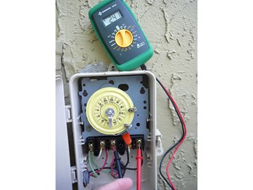
SELECT TEST POINTS - Voltage to the motor can be measured anywhere between the circuit breaker and the motor terminals One convenient test point is at the output terminals of your pump's timer, shown here. This picture shows the wiring inside the timer box. Three wires come in from the left of the box. Two are labeled INPUT and one GROUND. Generally, but not always, color of the wire is significant. If the two INPUT wires are red and black, they are both load wires and provide 240VAC. If they are white and black, white is neutral and black provides 120VAC. The green wires provide GROUND. The GROUND WIRES SHOULD BE ATTACHED TO THE GROUND SCREW JUST ABOVE TERMINAL "A". IT IS WRONGLY SHOWN IN THE CURRENT PICTURE AS GOING TO "A". There are 5 terminals in the timer box. The left most is A. The other four are labeled 1 to 4. The INPUT wires are connected to 1 and 3. The OUTPUT wires to 2 and 4. The OUTPUT wires are currently wired to the pump. Note: Not all timers are wired the same. This is the terminal configuration for an Intermatic timer. Check your timer to make sure which leads are the output lines.


Mike Posted: 8/29/2022
I need a new plastic wire hold-down. The white piece of white with the connectors for L1 - L4. Where can I get one?Reply
InyoPools Product Specialist Matt S. Posted: 8/30/2022
What is the part, model, or catalog number on your motor's label? A picture of the motor label would be most helpful.Reply
Anonymous Posted: 7/4/2021
Does the pool pump need to be on (running) when you check L1 and L2? Thanks!Reply
InyoPools Product Specialist Matt S. Posted: 7/23/2021
No, the pump does need to be running to test the lines. But the breaker needs to be "on" to measure the voltage.Reply
Anonymous Posted: 8/16/2021
The pump does or doesn’t need to be running?Reply
InyoPools Product Specialist Matt S. Posted: 8/17/2021
The motor should not be running when you test it.Reply
Anonymous Posted: 9/22/2021
How much drop is allowed in the running Voltage? My supply is 113 V. This drops to 94 V when the motor runs. Is this normal?Reply
InyoPools Product Specialist Matt S. Posted: 9/23/2021
That should not be happening. You may have an issue with your wiring or a breaker issue.Reply
Wilfred Rivera Posted: 8/22/2020
I finally figured it out. Your photos and multi meter explanations got me in the right track. My pool is now back in service. Thank you.Reply
InyoPools Product Specialist Matt S. Posted: 8/24/2020
Nice! I love hearing success stories.Reply
Wilfred Rivera Posted: 8/22/2020
I have a red wire, a white wire and a blue wire going to my motor. I also have the 120/ 220 switch and its currently set to 220. Im not sure which power setting to run it on.Reply
InyoPools Product Specialist Matt S. Posted: 8/24/2020
What is the part, model, or catalog number on your motor's label? A picture of the motor label would be most helpful. If this is a standard residential single speed pump, there is usually just three lines required for 120 or 240. The 240 volt has two hot wires and a ground, whereas 120 volts is one hot, one neutral and the ground.Reply
InyoPools Product Specialist Dennis R. Posted: 4/23/2017
Steve - If you have 120 V going to terminals 1 and 3, you should see 240 V across 1 and 3 when the breaker is on. With the red timer lever in the on position, you should see 240 V across terminals 2 and 4 as shown in Step 6. Concentrate on why you aren’t seeing 240V across 1 and 3. This is not a timer or pump issue.Reply
Steve Posted: 4/21/2017
I installed the new motor that you shipped to me and it does not work. Checking the voltage at the intermatic timer t104r, I have 120 volts from terminal L 1,2,3,4 to ground, but no reading between L 1 and 3 and L 2 and 4. I am suppose to have 230 volts to motor. Does this mean I only have 120V going to the motor?Reply
Inpools Posted: 2/13/2017
Step 6 - Not sure which picture you are referring to. The picture in Step 6 does show the meter probes on the output terminals 2 and 4.Reply
Anonymous Posted: 2/12/2017
Step 6 States: "Set your digital multimeter to 300 VAC and place the meter's probes on the OUTPUT terminals, 2 and 4."; however, the picture shows the meter's probes on the INPUT terminals 1 and 3. It seems to me that 1 and 3 will give voltage from main breaker to the timer, and 2 and 4 will give voltage from the timer. Is that correct?Reply
InyoPools Product Specialist Dennis R. Posted: 8/11/2015
bob - If you are getting 110V from Ground to terminals 1, 2, 3, and 4 on the timer than you should be getting 220V across 1 and 3 and 2 and 4. Sorry for the dumb question, but is your meter set up to read 220V and is the dial set on 220V?Reply
bob Posted: 8/11/2015
I followed this also and I do NOT get any voltage reading from 2 and 4 or from 1 and 3 (I should get 220V), but I get 110 Volts from Ground to L1, L2, L3 and L4Reply
InyoPools Product Specialist Dennis R. Posted: 7/12/2015
Testing motor - See our guide on "How To Use a Multimeter to Test a Pool Pump Motor - Winding Resistance" for information on test the motor windings. Also see our series of guide starting with "How To Replace AO Smith Motor Parts - Overview" for information on where a motor part can fail and how to replace the part.Reply
Anonymous Posted: 7/11/2015
I don't see how this test the actually pump motor.After all, the guide is titled, "How To Use a Multimeter to Test a Pool Pump Motor - Voltage". This only test the voltage running to the motor but not the motor itself it seems. How can I test the actual motor?Reply
InyoPools Product Specialist Dennis R. Posted: 12/9/2014
Voltage measurement - I'm not sure why you are not getting a voltage measure across the output terminals 2 and 4. There are 5 terminals. The left most is ground. The other four are labeled 1-4. Power comes into the timer on terminals 1 and 3 and goes out to the pump on 2 and 4. If you have a 240V timer and the timer is turned ON, you should get 240V across 2 and 4. You also get 240V across 1 and 3.Reply
Anonymous Posted: 2/27/2020
Are you testing the "load" terminals? If so, the pump switch needs to manually switched on, usually a lever that moves to left or right.Reply
Anonymous Posted: 12/6/2014
Great article. In step 6, I'm not getting any reading but if I test each individual connection I get 120v, any suggestions? Thank you.Reply
Anonymous Posted: 4/15/2019
if you are testing each individual terminal to ground what you see is normal 110 + 110 = 220.. Black lead on ground and red on terminal 1 then 2 then 3 then 4. You will see 110 to 122. What the previous answer did not tell you is 220 is two legs of 110 that is why two hot and one nuetral. google t104 timer click images and look for a 240 wiring diagram. It will help. to test the motor properly you need a megger meterReply