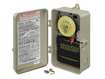
Running pool equipment 24 hours is usually unnecessary and expensive. Installing an Intermatic T104 timer is a great way to dramatically reduce run time and energy costs. The following steps will provide a guide on how to install the T104 timer. Note, timers vary with supply voltage. A T104 timer is used for 230V supply voltage. If you are using 115V supply voltage, you will need a T101 timer. The installation steps are the same for either.
Click Here to Find Your New Intermatic T104 Pool Timer 


JohnS Posted: 5/30/2017
i have 2 20amp circuits that are wired to box and one wire from panel shows 0 volts when grounded (neutral), the other 2 show 110.want it to control a new pump (set at 115) via timer and manual override.
a GFI outlet a on/off switch to swimming pool light
and (auto( temperature controlled /on/off switch that controls solar heating to pool.
the intermatic switch is a T104M model.
the A post is connected to the neutral, the other two wires to the line (which is 1 and 3 which have the associated clock wires), the pump is connected to the 2 and 4 post.
clock runs correctly but the electric motor / pump does not work when manual switch is ON. haven't bothered to test to see if timer will start pump.
without the pump wires connected, a voltage tester shows 0 when manual switch is off and 110 when on.
with the wires connected a voltage tester shows 0 when manual switch is off and goes off the chart when manual is set on.
1st, am I using the correct switch? if not, which one?
any ideas on how to fix or test?
Reply
InyoPools Product Specialist Dennis R. Posted: 5/15/2017
chipper - Make sure the white wires from the clock motor are attached to terminals 1 and 3 and not 2 and 4. If they are wired correctly, I'd replace the clock mechanism. See our guide on "How to Replace an Intermatic T104 Mechanism".Reply
chipper Posted: 5/12/2017
on trip is tight. the dial stops turning as soon as the timer shuts the pool downReply
InyoPools Product Specialist Dennis R. Posted: 5/11/2017
chipper - The "ON" and "OFF" trippers are different. See step 28. Make sure you have placed an "ON" tripper where you want the pump to be turned on. Also, make sure the tripper is on tight so it flips the switch on. If this doesn't correct the problem, you may need to replace the timer mechanism.Reply
chipper Posted: 5/10/2017
timer will turn off pool, but not start it. where should the manual switch be setReply
InyoPools Product Specialist Dennis R. Posted: 2/17/2017
wire gauge - The selection of wire gauge between the timer and pump depends on three factors: HP, supply voltage, and distance. An 115V pump will use twice the amperage as a 230V pump. If the distance to your pump is less than 50 feet, for a 1HP or less pump, on 230V you would need 14 gauge wire - for 115V you would need 12 gauge wire. If the distance to the pump is between 50 feet and 100 feet and you have a 1 HP pump, 230V requires 12 gauge, 115V requires 8 gauge. For a 3/4 HP pump, 230V requires 12 gauge, 115V requires 10 gauge.Reply
Anonymous Posted: 2/16/2017
What gauge/type wire should be used from timer to pool pump?Reply
InyoPools Product Specialist Dennis R. Posted: 12/12/2016
Timer wiring - Are these two additional wires than what is shown in this guide and where are they. I would have to know more about the make and model of this timer to help you.Reply
Anonymous Posted: 12/11/2016
The new timer has two black wires that the old timer doesn't have. Where do they go?Reply
InyoPools Product Specialist Dennis R. Posted: 11/22/2016
Tino - I'm assuming you are trying to install a timer for a 220V system since you have two hot wires coming into the timer. And I'm not sure which timer mechanism you have but the T101M mechanism has the same 5 number of terminals as the T104M mechanism. A major difference between the T101 and T104 timers that you have to consider is the timer motor. The T104 runs on 220V; the T101 runs on 110V.Reply
tino Posted: 11/21/2016
I have the 101 series and I have two hot lines coming in and the timer only has tree terminals instead of five is there a way to ether buy extra terminals or there is deferent wiring options.Reply
InyoPools Product Specialist Dennis R. Posted: 8/26/2016
mrjaydeeone - You should have a label inside the cover of the timer box that identifies your timer as a T101 for 110V, or a T104 for 220V. If that label is gone, take the timer mechanism out and look at the back of the timer motor. It will be labeled 110V or 220V specifying what voltage it uses. If your clock is not moving, it is likely that the motor has failed and you would only have to replace the motor. See our guide on "How To Replace an Intermatic T104 Clock Motor". Or if the whole mechanism has failed due to jammed gears, see our guide on "How to Replace an Intermatic T104 Mechanism".Reply
mrjaydeeone Posted: 8/26/2016
I just purchased a house with an AG Pool. And it has an intermatic timer for the pool pump and filter. The timer is not working. The close does not move. How can I determine if I have a 110 volt or 220 volt? on the plate for the timer it is stamped D10694. Thank youJason
Reply
InyoPools Product Specialist Dennis R. Posted: 8/17/2016
T104 timer wiring - When wiring a T104 Timer for 220V, the white wire in a 3 wire plus ground cable is not used. It is generally capped off inside the timer with a wing nut.Reply
Anonymous Posted: 8/16/2016
Where does the common or White wire get connected to? Usually a 220Vhas three wires Black,Red White and ground (Green / Bare )
Reply
InyoPools Product Specialist Dennis R. Posted: 8/10/2016
T104M replacement - It not clear why you have 4 wires coming from the panel. For a 220V installation, you normally have one hot red and one hot black coming from the panel and attaching to terminals 1 and 2. A green ground would also be attached to the grounding lug. Power for the clock would come off of terminals 1 and 3. See our guide on "How to Replace an Intermatic T104 Mechanism" for more information.Reply
Anonymous Posted: 8/9/2016
Question: I am replacing a T104M that has stopped working (with another T104M) and there are four wires coming from the panel(two black and two red). For the existing (broken) timer, the two black wires from the panel are connected to the two white wires from the clock motor, and the two red wires from the panel are connected to terminals 1 and 3. [There are also two red wires that connect to the equipment, which are connected to terminals 2 and 4 as you would expect.Should I (a) just copy this setup for the new timer (i.e. disconnect the white clock motor wires from terminals 1 and 3 and connect them directly to the two black wires from the panel, and connect the panel red wires to terminals 1 and 3), or (b) leave the clock motor wires connected to terminals 1 and 3 and also connect the black and red panel wires to terminals 1 and 3 (and if so,should I connect one red and one black to each of terminals 1 and 3), or (c) something else...?
Thanks!
Reply
InyoPools Product Specialist Dennis R. Posted: 7/5/2016
Jboy - The A post is only used in very special circumstances and is generally not wired to anything. Check your wiring against this guide again to see if you missed something.Reply
Jboy Posted: 7/1/2016
question What should the A post be connected to ? In the wiring diagram is says neutral .. when I connect it to the white neutral bar in the fuse box it trips the gfi same if I connect it to the ground bar ... this is a double pole switch with GFI.When not connected to anything the timer is not working??
Reply
InyoPools Product Specialist Dennis R. Posted: 3/26/2016
DavidJ - The easiest way to "disable" the timer is to pull off the "ON" and "OFF" trippers. See Steps 26-29 of this guide for instructions on putting the trippers on (or taking them off). The motor on the timer will still run, but it won't engage the on/off switch.Reply
DavidJ Posted: 3/24/2016
Just bought a house that has a T104 on the hot water heater. How do I disable the timer so that the heater functions normally as it would without the timer?Reply
InyoPools Product Specialist Dennis R. Posted: 3/19/2016
Dave - Sound good to me. Check the wiring again. On a T104, the inputs are on terminals 1 & 3 and the outputs on 2 & 4. Make sure that the circuit breaker to your timer is large enough to handle both functions.Reply
Dave Posted: 3/18/2016
Hi guys, I recently bought a Pentair vs super flo pump w/timer from you and am ready to install. I have an Intermatic T104 timer that is also used to control on roof solar heating. Since the new pump has it's own digital timer can/should I wire this to the 'line' terminals (1&2) so that it has continuous power? I plan on keeping the solar on 'load' terminals (3&4) to control with T104 timer.As usual, thanks for all the help!
Reply
InyoPools Product Specialist Dennis R. Posted: 3/14/2016
Doug S - There is a set of contacts on the backside of your timer that may not be closing properly. Look at our guide on "How to Replace an Intermatic T104 Mechanism" to see how to remove this mechanism and see the contacts. You do not have to remove the wires to see behind the mechanism. Make sure the power is OFF. When you manually switch the timer on, you should see both of these contacts close. If they do not, I would replace the mechanism. If they close properly, recheck your wiring.Reply
Doug S Posted: 3/12/2016
I have it wired correctly but I can not manually shut the pump off with the on/off switch nor does it cut off when it reached the clock trippers. Any suggestionsReply
InyoPools Product Specialist Dennis R. Posted: 3/7/2016
George - The knockout plates are cut out most of the way around and are only held in by thin uncut tabs. Force a small screwdriver into the cut out area and pry the plate out. The uncut tabs will break off.Reply
George Posted: 3/5/2016
How do I open the knockout holes on the timer? A procedure please!George
Reply
InyoPools Product Specialist Dennis R. Posted: 2/29/2016
Captain - I have a call in to confirm these answers with the Intermatic rep but here is my understanding now:1- According to the fine print in the wiring figure, the "A" connector is used with 277/480 volts not generally available to a typical resident.
2- If you have 220V coming in on the black and red wires and the green is ground, the forth supply white wire is extra and should be capped off.
3- This timer is limited to a total of 40 amps so would not handle a 20 amp pump and a 50 amp heater. I think most users rely on the "no flow" switch within the heater to shut off the heater when the pump is turned off.
Reply
Captain Posted: 2/26/2016
1.) What is the "A" connection for on the T-104R?2.) Besides Line #1 (Black), Line #2 (red) and ground (copper), I do have a nuetral (white)wire that is not connected to anything in the timer box. Do I connect it to anything? or do I just cap it off?
3.) Can I wire this timer (T-104R) to start both my pump and heater at the same time? Both are 220VAC, The pump is on a 20amp breaker and the heater is on a 50amp breaker.
Reply
Patridr Posted: 2/10/2016
Read your directions to install a new T104R Timer. I'm a guy who hates dealing with anything electrical and any more than three wires baffles me. You made it easy and SAFE... Thanks a lot, DavidReply
InyoPools Product Specialist Dennis R. Posted: 10/9/2015
dj- Unfortunately, we do not have that information. I suggest calling Intermatic direct and seeing if they can provide a wiring diagram. Their number is 815-675-2321.Reply
dj Posted: 10/8/2015
i need to control a 1hp. 3phase, 460volt, with a timer i know one can do it with a 230v intermatic timer, Can you supply the wiring diagram for the 1hp submersible water pump motor?Reply
InyoPools Product Specialist Dennis R. Posted: 9/13/2015
Pete - I assume your clock motor is good since it sounds like it was advancing the dial when the power to the pump was on. Check that the white motor wires are attached to terminals 1 & 3, the supply voltage, as shown in Step 20. Then make sure the dial is engaged into the clock gears by rotating it left and right slightly.Reply
Pete Posted: 9/13/2015
I have completed the wiring as instructed. If I manually flip the on switch the timer will complete the cycle and shut the pump off. Once the unit is off the timer does not continue to move, it stays at the time the unit shut down. What am I missing??Reply
InyoPools Product Specialist Dennis R. Posted: 8/9/2015
timer hookup - You have to make sure that your salt system shuts off when your pump is off. So somehow in your wiring configuration you have to tie them to the same timer. If your pump bypasses the external timer, there is a chance that the pump could be shut off while the salt system is left on.Reply
Anonymous Posted: 8/8/2015
I have the intermatic timer that was controlling a single speed pump and salt system. I have replaced the single speed pump with a variable speed with its own control panel. I still want to use the timer for the salt system but not the new pump. Should I connect the pump to 1 and 3 just to send power to the pump bypassing the timer?kris
Reply
InyoPools Product Specialist Dennis R. Posted: 8/6/2015
Bubba - Not sure what you mean by a double 104 timer. If you want to turn the filter pump and booster pump on at the same time, wire them together to terminals 2 and 4, the output terminals on the timer. See step 20 of this guide. Picture shows one wire going to 2 and to 4. You would have 2 wires on 2 and on 4.Reply
Bubba Posted: 8/4/2015
I need wire diagram to install a double 104 timer on a filter pump and booster pump.Reply
InyoPools Product Specialist Dennis R. Posted: 7/10/2015
WW - Yes the wiring is the same for a T101 as for a T104.Reply
WW Posted: 7/9/2015
Question:Is wiring for T104 the same for T101?Reply