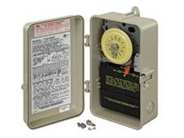
Running pool equipment 24 hours is usually unnecessary and expensive. Installing an Intermatic T104 timer is a great way to dramatically reduce run time and energy costs. The following steps will provide a guide on how to install the T104 timer. Note, timers vary with supply voltage. A T104 timer is used for 230V supply voltage. If you are using 115V supply voltage, you will need a T101 timer. The installation steps are the same for either.
Click Here to Find Your New Intermatic T104 Pool Timer 


InyoPools Product Specialist Dennis R. Posted: 7/7/2015
Ray - The model numbers tell you which voltage you have. If you have a T101P timer, you are set up for 120V. If you had 240V, you would have used a T104P timer.Reply
RAy Posted: 7/6/2015
I have an Intermatic T101P Timer currently for my pool that needs replacing. Is there a way for me to see whether my current timer is 120V or 240V without a volt meter? Probably a silly question but I don't often deal with electricity! Thanks!Reply
InyoPools Product Specialist Dennis R. Posted: 6/30/2015
Confused - Glad we could help and thank you for the feedback. We seldom get responses and they are much appreciated.Reply
Confused Posted: 6/29/2015
INYOPOOLS.COM thanks for your assistance and on your advice and checking voltage with my multimeter, the voltage to my T104 is only 120V. I will contact my electrician to correct this problem.Reply
InyoPools Product Specialist Dennis R. Posted: 6/28/2015
Confused - These timers have been around a long time are generally very reliable. Recheck your wiring and ground. Then I would suggest calling Intermatics at 815-675-2321. They should be able to troubleshoot this problem.Reply
Confused Posted: 6/27/2015
Sorry, my initial post should have read that my T-101 timer switch operates the pool pump. It still works fine (20 Years). My T-104 operates my pool light. So my pool has two separate switches one for the pump the other for the light. It is the clock motor in my new T-104 that was replaced and the replacement is also not working. Thanks for your assistanceReply
InyoPools Product Specialist Dennis R. Posted: 6/27/2015
Confused - You stated that your old timer was a T101 and you replaced it with a T104. Did you change the supply voltage to the T104? T104 runs off of 220V and T101 off of 110V. If this is not the issue, give Intermatics a call at 815-675-2321. They should be able to troubleshoot this problem.Reply
Confused Posted: 6/25/2015
I've had my pool for about twenty years now. My Model T101 timer switch that operates the pump still works fine (20 years) my T104 clock stopped about a year ago. Purchase a new complete time switch installed it turned it on but did not operate. Then I manually touched the wheel and the clock started working. Everything worked fined until there was a power break and the clock would not start until it was 'touch' to get it started again. Purchase a new clock motor and installed..and the same thing happens. Is this a problem with the clock model WG1573-5E 208/277V 60HZ??Reply
InyoPools Product Specialist Dennis R. Posted: 6/4/2015
Clay - If this is your second timer, I doubt that it is a faulty timer. The only thing I can think of is that the on/off tripper might be installed wrong. Check your installation of the trippers against the pictures in Steps #27 and #29.Reply
Clay Posted: 6/2/2015
Installed a new timer and the clock will rotate but it will jam when it gets to the on or off switch. It will run manually so the main and buster pumps work just fine. What could be causing this? I took one back to the store and installed another, so I don't think it is the timer.Reply
InyoPools Product Specialist Dennis R. Posted: 5/30/2015
lj- Check to make sure all the input and output connections to the timer are tight. Else you might try replacing the timer mechanism. See our guide on "How to Replace an Intermatic T104 Mechanism" It's the same as replacing a T101 mechanism except T104 is for 230V. Buy the T101 Mechanism.Reply
lj Posted: 5/28/2015
T101 Drops voltage on the load side when timer turned on. 120v on incoming line when off, drops to 106v on the load side. Not able to turn the pump on, consistently cyclesReply
InyoPools Product Specialist Dennis R. Posted: 5/12/2015
Timer motor - Yes, the clock dial should turn once every 24 hours to trip the system on and off. Sounds like you have a bad timer motor. See our guide on "How To Replace an Intermatic T104 Clock Motor" for more information. It's a relatively easy repair.Reply
Anonymous Posted: 5/11/2015
Just opened our pool and the clock dial is not turning. Should it always turn, even with the manual lever on? Sorry, I'm sure it's a silly question, I'm new to pools:)Reply
InyoPools Product Specialist Dennis R. Posted: 4/20/2015
Evaleen - An extra "A" terminal is provided on most 2- speed motors to allow foe switching between high and low speeds on a 2-speed motor. See our guide on "How To Set Up the Intermatic Pool-Spa Control System for 2-Speed Pump" for an example of one application.Reply
Evaleen Posted: 4/18/2015
what is the A terminal used for?thanks
Reply
Eddy V Posted: 3/25/2015
Great tutorial! Inyopools is always my 1st stop when I need to know anything about my pool. I just installed a T104 timer according to you instructions...works like a dream. Thanks again!Reply
InyoPools Product Specialist Dennis R. Posted: 8/6/2014
Krista - I don't know why the timer would work fine for two days then stop working. The T104 timer is for 220V. If your supply voltage is 110V, I don't think it would have worked for two days. Give Intermatics a call at 815-675-2321. They may have an answer.Reply
Krista Posted: 8/5/2014
I just installed a new intermatic T104M for my swimming pool pump and salt water system. It ran fine for two days and now it has begun to run for a few seconds and turn off. The wires from the breaker are hooked up to post 1 & 3 and the wires to the pump and system are hooked up at 2 & 4. Any pointers as to why it keeps shutting off is appreciated. ThanksReply
InyoPools Product Specialist Dennis R. Posted: 6/18/2014
T104 timer - A T104 timer can handle 40 amps. Customers generally run a pump and salt system on one timer. Check you tatal amperage, but I think adding the heater would exceed 40 amps. Most heater are set up to shut off when the minimum flow required drops below 40 GPM or so, so they would shut off them self when the pump is turned off.Reply
Anonymous Posted: 6/17/2014
Can this timer handle more than two loads? What I mean is, can I connect pool pump, heather and salt system to it ?Reply
InyoPools Product Specialist Dennis R. Posted: 5/31/2014
Pat - Looking at step 14, since this is a 220V timer, all lines you see are hot. There is no neutral. The white lines on terminals 1 and 3 go to the back of the timer to power the clock motor. The red and black lines on terminals 1 and 3 are the supply lines coming from your breaker box. Both are hot for 220V. See our guide on "How To Replace an Intermatic T104 Clock Motor" for a different look at this.Reply
Pat Posted: 5/30/2014
What about the timer wires ? The two white wires ,are they both hot? Or one neutral one hot when hooking up 220v I have one to the neutral one hot and the timer is not working I noticed in the picture they both seam to be going to terminals 1-3?Reply
InyoPools Product Specialist Dennis R. Posted: 5/28/2014
Larry - I would measure the voltage coming into the current timer. Here's our guide on measuring voltage: How To Use a Multimeter to Test a Pool Pump Motor - Voltage.Reply
Larry Posted: 5/27/2014
My old timer has the paper inside the door torn off. How do I tell which model I need? The breaker in the main panel is a double labeled 10 amp, 120 - 240. Since it is a double breaker does this mean it is a 240?Reply
InyoPools Product Specialist Dennis R. Posted: 5/25/2014
Joe - You have the right timer. T104 is the most common timer used to control pool pumps. T104R3 is the metal version for 220V. T104P3 is the plastic version. Both are commonly used outdoors in the weather. They have a rubber seal on the door. Lighting control is one option. And I don't know why they said "For indoor Installation" except to indicate that it could be installed indoors also. Check to make sure it has the rubber seal.Reply
Joe Posted: 5/25/2014
Our General Contractor (Plumbing and Electrical) recently installed (Friday, 23 May, 2014) our new Hayward 1HP Super Pump (a replacement)and also an Intermatic 24h Mechanical Time Switch (Model T104) since we wanted to try running our pump system on an 8-10h cycle to lower the cost of operation this Summer. I wanted to install an Intermatic Model with the plastic enclosure since our electrical system is located outside in the elements. The only Intermatic Timer he could find in town was Model # T104 (208-277 VAC-60HZ / DPST) and it is in a metal enclosure. Later, after the new pump and timer was installed, I noticed that the front of the box (lower left corner) stated the following: "Great for Controlling Incandescent, Fluorescent, LED, and CFL lighting". Also, "For Indoor Installation".Unfortunately I cannot contact our contractor since he is away for Holiday weekend and will not return until Monday evening. Our pool is scheduled to be open on Wednesday, 28 May (only 3 days away) and my wife and I are concerned about whether this was the correct timer to install.
ANY QUICK INFORMATION YOU COULD GIVE US WOULD BE GREATLY APPRECIATED. I WOULD LIKE TO BE ABLE TO TALK WITH OUR CONTRACTER UPON HIS RETURN TO TOWN IF THIS WAS NOT THE CORRECT TIMER TO USE. We have very little time before the pool people show-up to open the pool and crank-up the new Hayward pump motor.
Thank You .... I surely hope we hear back from you ASAP. You have been a great help in other questions we had about installing a timer and how it would NOT hurt our new motor pump.
Joe
Reply
Pete Posted: 11/7/2013
Simple and direct. That is exactly what I needed!Reply
Anonymous Posted: 9/14/2013
After wiring this timer up to my pool pump. Hit the breaker clintching my teen in antisipation of having to change the fuse! The diagram on the timer was not simple enough.
THANKS for this IDIOT PROOF demonstration. "The Check is in the mail"...
George
Reply
InyoPools Product Specialist Dennis R. Posted: 9/13/2013
timers - The white and black wiring is generally the convention for 110V systems. Timers are sold for 110V systems (T101) and 220V systems (T104). Make sure you have the correct timer for your pool system.Reply
Anonymous Posted: 9/12/2013
my old timer the timer motor leads connected to one black the other to white why new one in store both to black kReply