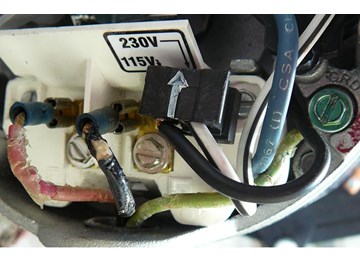
Pool pumps are wired to run on either 230V or 115V. Most are run on 230V and are preset at the manufacturers at 230V. If you are going to wire your own pool pump, you must first know what voltage is coming to your pump from the house circuit breaker. Also you must ensure that the electrical supply agrees with the motor's voltage, phase, and cycle and that all electrical wiring conforms to local codes and NEC regulations. If you are unsure of this voltage or are unfamiliar with electrical codes and regulations, have a professional electrician wire your pump for you or at least check your work.
Failure to wire the pump correctly can cause electrical shock or can damage your pump motor and void your warranty.


Mike Posted: 3/16/2023
I'm replacing a yr-old Century motor and took a pic of the old wiring conx, where black is on L2 and white is on L1 - the opposite of your photo in Step 8 (which I see in a 2021 comment that you changed). Should I be following the orig wiring (repl w/exact same pump, 115A) or your diagram? Also, I don't see how to attach a photo?Reply
InyoPools Product Specialist Matt S. Posted: 3/17/2023
Follow the wiring instructions on your new motor's label. Not all motors have the same wiring instructions.Reply
Anonymous Posted: 5/6/2022
Thank you for the video. It was very helpful. My problem is when i put all three wires through the small hole, i broke the prong that’s connected & protecting the wiring. Can i find replacement covering with prong @ Lowes. It was very difficult getting the wires thru hole bc they have a plastic covering that is bigger than the hole. Your pump is just like mine. Green ground wire has prongs on it to fit underneath screw. My old one was set 115V. Thank you so much. Pics say everything. ?? Do they need that plastic covering?Reply
InyoPools Product Specialist Matt S. Posted: 5/11/2022
If you take a picture of the part or the actual piece that broke off into the store, they should be able to get you a replacement. The clip you are referring to sounds like something that can be crimped on pretty quickly.Reply
Ricky Posted: 2/25/2022
Hello. I bought a new pool pump and it only comes with withe, black and green wires. (You can’t detach the wires because they are soldered on). My supply box has a black, black and green wires. It’s 2 hot lines and no neutral. Can I plug them to this pump and if so how? Any advice about this situation will help. Thank you.Reply
InyoPools Product Specialist Matt S. Posted: 2/28/2022
I am not familiar with that style of wiring set up in the new pump you are describing. If this is a new pump, look at the manual or contact the manufacturer if the wiring diagram on the motor does not match up exactly what you have. The wiring you describe is not the standard type found on most pool pump motors.Reply
Mike Posted: 11/6/2021
Hi I have a red wire a purple wire and a black wire also a green wire coming from my control box what terminal I put the purple wire my system runs 230v 2.4hp century motorReply
InyoPools Product Specialist Matt S. Posted: 11/10/2021
Look at your motor's wiring diagram label on its side. Does it show where to put a purple wire? Purple is not a standard color coding for an electrical wire in the US. I couldn't tell you where it is meant to go because I do not know what it does. How was it connected to your old motor?Reply
Eddie Posted: 9/29/2021
I'm wiring a B2853 pump and have a gray wire and a white wire. I haven't turned in on yet, but I wired it for 115. The one I'm replacing had the prong set on 230 tho. And it's on a double breaker switch. The more I think about it, I think the white wire is live. Not really a question, I'm just confused.Reply
InyoPools Product Specialist Matt S. Posted: 9/30/2021
It sounds like you have 230 and not 115. Unfortunately, not every electrician or DIY-er will follow electrical wire color code guidelines. If you want to be super sure, I'd test the circuit with a multimeter (How To Use a Multimeter to Test a Pool Pump Motor - Voltage.) Hopefully, you have not turned on the motor. A motor set to run on 115V can be damaged if 230V is applied. But if you apply 115V to a motor set to run on 230V, there shouldn't be any ill effects besides it not running.Reply
Rob Posted: 5/22/2021
In step 8 I am having trouble shifting the black tab down. I have tried to dislodge it by pulling toward me and it’s not working . Can you please help?Reply
InyoPools Product Specialist Matt S. Posted: 6/4/2021
What is the part, model, or catalog number on your motor's label? A picture of the motor label would be most helpful.Reply
Anonymous Posted: 5/16/2021
I have an old motor that has 1 white wire and 1 blue wire and a ground. Is there any way of knowing if this is 230 or 115? All the labels on the motor are worn off and I need a replacement.Reply
InyoPools Product Specialist Matt S. Posted: 5/21/2021
Get a multimeter and test the voltage of the individual lines. The only way to know for sure is to test it.Reply
Jason Posted: 5/10/2021
Hello, I am trying to wire a Hayward Super Pump 1-1/2 hp W3SP2610X15. I have a 8/3 wire run to the pool. Does the ground wire need to be insulated.Reply
InyoPools Product Specialist Matt S. Posted: 5/13/2021
I suggest an insulated ground wire. Bonding wires do not need to be insulated.Reply
Anonymous Posted: 5/7/2021
I have a hayward 1 1/2 hr pool pump. Model C48L2N134B1. There is a black wire hanging out of the motor housing with a clip on it. don't seem to see where it hooks up to. Any Help?Reply
InyoPools Product Specialist Matt S. Posted: 5/13/2021
Does the motor have an intact label? If so, there should be wiring instructions on it. Sometimes the MFG list extended wiring instructions that show internal wires in the schematic.Reply
TL Posted: 5/5/2021
At Step 8, the following is confusing, as usually, the black is delivering 115v and the white is neutral (0v). Looks like white and black are swapped? "Attach the white (115 V) wire to terminal 1 of Line 1 (L1). Attach the black wire (0 V) to terminal 3 of Line 2 (L2)."Reply
InyoPools Product Specialist Matt S. Posted: 5/13/2021
Good catch, I've edited that step. Thank you very much.Reply
Anonymous Posted: 5/15/2021
Sorry still confused on L1 L2 wiring. Is the black L1?Reply
InyoPools Product Specialist Matt S. Posted: 5/21/2021
Black = L1, White = L2Reply
Anonymous Posted: 5/8/2022
from my timer box I have 2 black wires and one green. how to I know which black wire to attach to f1 or f3. The motor is a ust1102 aa5/230, and it is set to 230.Reply
InyoPools Product Specialist Matt S. Posted: 5/11/2022
It doesn't matter which wire goes to which terminal; with 230-voltage, both black wires carry the same power.Reply
Lc Posted: 4/7/2021
My pool pump is wired.how do i wire a timer to it and do it need a separate breakerReply
InyoPools Product Specialist Matt S. Posted: 4/8/2021
First, we would need more information. What is the model, part, or catalog number on your motor label? Second, what type of timer are you looking to put on the circuit? A basic on and off type of timer, or something more complex like an automation system?Reply
David D Posted: 4/1/2021
What is the name of the elbow? mine was plastic and in removing my old one it broke. Is it supposed to be metal? the screw size is .70, not 3/4. Is there a specific size for pool pumps?Reply
InyoPools Product Specialist Matt S. Posted: 4/1/2021
You should be able to find one at a hardware store by asking for an electrical conduit elbow. You could also Google a picture of it, then bring it into a hardware store so they can get what you need. The standard size is 3/4" for pool pump motors.Reply
Dave Posted: 8/12/2020
If I have a pump that can be wired either 115 or 230 and my power supply is only 115 but the pump is currently wired for 230 will it cause the pump to underperform?Reply
InyoPools Product Specialist Matt S. Posted: 8/26/2020
The motor may not turn at all. If you know the voltage of your power source, and that the motor is currently set to a different voltage, I would just switch it to the right setting.Reply
Erica Posted: 8/12/2020
My old motor didn’t have a ground wire attached. Do I still need to attach a ground wire to the new motor and if so where do I attach the other end of the ground to?Reply
InyoPools Product Specialist Matt S. Posted: 8/20/2020
The ground wire should go back to the timer or the breaker.Reply
Erica Posted: 8/11/2020
My old motor didn’t have a ground wire attached. Do I still need to attach a ground wire to the new motor and if so where do I attach the other end of the ground to?Reply
InyoPools Product Specialist Matt S. Posted: 9/3/2020
Your motor needs a ground wire. The ground wire is connected to the metal housing of the breaker box. I'd make sure to higher an eletrician to get you set up.Reply
Bill Posted: 8/1/2020
I wire motor for 115v and it does not run but if switch the plug to 230v it runsReply
InyoPools Product Specialist Matt S. Posted: 8/21/2020
Are you sure the circuit you are using is 230 volts? Have you double/triple checked the wiring on the motor to verify it is indeed set to the correct voltage?Reply
Vinny McDermott Posted: 7/22/2020
I installed a new Hayward Super Pump which came with two different power leads for 110 vac and 230 vac. When I went to hard wire the pump, of course I misplaced the 230 vac lead. Any ideas as to the Hayward part number. ThanksReply
InyoPools Product Specialist Matt S. Posted: 9/3/2020
I'm sorry, but I am not sure what you are referring to when you say it came with two leads. Inground pump motors that are dual voltage (accepts 115 or 230 V) usually just have a jumper or a knob on the terminal board to switch it to the desired voltage. The pumps that I have seen fresh of the box do not include conduit or wiring.Reply
Brian Garnick Posted: 7/6/2020
Very helpful, thanks!Reply
InyoPools Product Specialist Matt S. Posted: 8/26/2020
You're welcome! Thank you for reading.Reply