Pool pumps are wired to run on either 230V or 115V. Most are run on 230V and are preset at the manufacturers at 230V. If you are going to wire your own pool pump, you must first know what voltage is coming to your pump from the house circuit breaker. Also you must ensure that the electrical supply agrees with the motor's voltage, phase, and cycle and that all electrical wiring conforms to local codes and NEC regulations. If you are unsure of this voltage or are unfamiliar with electrical codes and regulations, have a professional electrician wire your pump for you or at least check your work.
Failure to wire the pump correctly can cause electrical shock or can damage your pump motor and void your warranty.


Anonymous Posted: 6/3/2014
Just got a Jandy Stealth SHPF 1.5 from your store, pre-wired for 230V. The Jandy has wire connectors similar to the picture in Step 7. My feed is 230V. Shouldn't I be able to just connect the red wire to the screw on L1 and the black wire to the screw on L2 and the green wire to the ground screw? What is the importance of terminal 1 and 3?Thanks!
Reply
InyoPools Product Specialist Dennis R. Posted: 5/20/2014
mike in Jax nc - Make sure that your supply voltage matched your voltage configuration for you pump - 115V or 220V. Then check that all your wire connections are tight. If your power cord is old, you might consider replacing it. If your power line to the pump is long, you may need a higher gauge wire.Reply
mike in Jax nc Posted: 5/17/2014
I just installed a replacement motor to my pump, its a 1.5 hp when I turn it on it it clicking and running very slow? Any ideas what can be wrong?Reply
InyoPools Product Specialist Dennis R. Posted: 5/12/2014
cotta - Look at the label on the motor for the motor's voltage. If it only says 115V, you have to wire it to 115V supply. If it says 115/230, the motor can be wired for either 115 or 230V. The motors are generally shipped from the factory in 230V configuration. I would check the white lead that you have connected to ground with a multimeter to make sure it is 0 Volts. If your motor is running now as you have wired it, you are probably OK. Motor's will often run hot to the touch.Reply
Anonymous Posted: 5/11/2014
Awesome Video and instructions. Bought the new motor and pump rebuild kit from you guys so it was great to have instructions that covered the slightly different wiring of the new motor. Thanks again.Reply
cotta Posted: 5/9/2014
the pool motor is connected and ready to go on the flotec 1hp motorin connecting the motor with one with 230 nothing has to be done to the
motor? or does it?
we connected the black wire to the one hot lead and the red wire to the other hot lead, and the white to the ground ? the motor seamed to get a little warm ??????? can help me with this?
Reply
InyoPools Product Specialist Dennis R. Posted: 5/9/2014
ground wire - Use a multimeter to determine which of the three wires is ground. Two will have 120V and one [ground] will have 0V.Reply
Anonymous Posted: 5/8/2014
I have a 230 wiring. Black White and White. no green or red. one is not as bright white and maybe a little yellow. Which goes where?Reply
InyoPools Product Specialist Dennis R. Posted: 4/27/2014
pump hums - Sounds like a mismatch between supply voltage and the voltage your pump is set for. Check the incoming voltage with a multimeter and then check the configuration of the motor voltage. Your user's manual should show you how to configure your motor voltage.Reply
Anonymous Posted: 4/26/2014
I replaced my pentair pool pump and wired as per previous pentair pump. Green ground blue to L2,and black to A. Pump just hums when breaker is flipped on. I dont know if newer pump is wired different.Reply
InyoPools Product Specialist Dennis R. Posted: 4/25/2014
techknow - If your pump is on 220V, 12 gauge is fine for 25'. If your pump is running on 115V, you should go to 10 gauge to be safe.Reply
techknow Posted: 4/23/2014
Hi Inyopools support. I purchased a Hayward Aquatrol Return Jet salt water system. The way my above ground pool is set up, I have the pump in a shop, and plumbed to the pool. I want to install the chlorinator on the deck, and run a piece of conduit underground to the pump in the shop. Question: This is about a 25 foot run tops, can I use 12 gauge wire or do I need to go with a 10AWG? It's a 1.5HP Waterco pump. I can't mount the Aquatrol control box in the shop because the 15 foot cord to the cell is not long enough. I bought the RJ model because it was less expensive.Reply
InyoPools Product Specialist Dennis R. Posted: 3/7/2014
rsacock - It sounds like sometime is rubbing inside the pump. Take the motor out again and check to make sure the impeller is on tight and there is no debris between the impeller and the diffuser.Reply
rsacock Posted: 3/2/2014
Ordered replacement motor with exact specs of existing motor. New pump is wired per these online instructions because there was no manual included with new motor. Motor makes a terrible amount of noise, gives very little water pressure, and cuts off after 10 seconds. Selector is set for 115v as the supply is 115v. Very frustrated with this problem.Reply
InyoPools Product Specialist Dennis R. Posted: 11/24/2013
Jeff - I'm not sure what your wiring setup is. Most 2-speed motors are controlled by an external switch of 2- speed timer. See our guide on "How To Wire a PE153 Digital Timer to a 2-Speed 230V Motor". It may not answer your question specially, but it will give you an idea of what's involved in wiring a 2-speed motor.Reply
Jeff Posted: 11/20/2013
Replacing a motor on my Hayward Tristar 2 speed pump. Old motor was an Emerson, new one is a Century. Anyway, the connections on each are labeled differently. The old connections on motor and as hardwired now are C-blk, H-red & L-blue. The one I know for sure is the ground-grn. New motor As received and wired is A-red, L1-blk& L2-wht, and of course the green ground screw I know. How do I match up the old hard wires with new motor. The leads on new motor will come off...
Thanks foe the help on this site.
Reply
InyoPools Product Specialist Dennis R. Posted: 10/27/2013
pentair motor - With AC motors it does not matter. Either of the two red wires can be connected to either L1 or L2 terminals.Reply
Anonymous Posted: 10/24/2013
Hello, I have a pentair motor I am replacing with a pentair motor. 230V My wires are 2 red and 1 green. How do I know which red goes to which post? ThxReply
InyoPools Product Specialist Dennis R. Posted: 10/21/2013
cuffer - I don't know how your spa control pack is wired but look at Step 3 in our guide on "How To Wire a PE153 Digital Timer to a 2-Speed 230V Motor'. It will give you some insights in how a two speed motor is wired. In this configuration, L2 is always hot. For high speed, circuit/switch 1 is on - the switch between terminals 3 and 4 is closed and power flows to L2 - switch between 5 and 6 is open. For low speed, circuit 2 is on - the switch between terminals 5 and 6 is closed and power flows to A - switch between 3 and 4 is open.Reply
InyoPools Product Specialist Dennis R. Posted: 10/21/2013
HOTTUBFVR - I assume the two blue wires are your two power wires coming from your circuit breaker to your pump. The label on the pump motor should show you how to wire this specific pump. In general the two wires go to L1 and L2.Reply
cuffer Posted: 10/20/2013
I am needing some advice... I recently replaced my spa control pack and now the 230v motor is shutting down when put in high speed mode(thermal switch on motor)I have checked the voltage at the black wire in low and it reads 123v and when put on high the red wire reads 123v and 0 on the black wire... is this correct?Reply
HOTTUBFVR Posted: 10/20/2013
my pump controls both the the spa and the pool i recintly relaced an ceturion 1 1/2 hp moter with a sta -rite 1 1/2 moter but the old moter was wired with blue wires going to a and b and ground the new one is a or L1 or L2 and ground the is a 10 year old pentair system wiring grond no prob but two blue wires? whatto do?Reply
InyoPools Product Specialist Dennis R. Posted: 9/30/2013
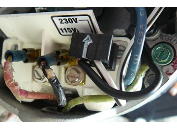
No Electrician - It's hard to understand your problem without a picture of your wiring, but.. Look at Steps 7 and 16 on this Wiring Diagram. Step 7 spreads the components out so you can see the wiring better. The "black part" you are referring to may be the overload protector. It has a blue wire coming from it and going to L1. If your blue wire is going to L2 you have something different. In any case this is the back wiring to L1 and L2. You would still attach your supply wires to L1 and L2.Reply
Horace Posted: 9/28/2013
My hot tub leaked all the water out; filled it back up, turned it on, saw that the single pump motor was leaking between wet & dry section. Ordered a new one just like the old. Only diff, the new one had the capacitor instead & the wire was a little diff on the outside (the wires were covered in the old ones) New one has two places for the BLACK and the WHITE coming from the board. The wires they can connect to are YEL/BLACK and YELLOW. My question: BLACK to YELLOW/BLACK? (that's what we did; hot tub now turns on for 1/2 second then nothing! HELP!Reply
No Electrician Posted: 9/26/2013
I bought new pump supposedly just like old one to make switching out easy. But the new one has a black part in the back next to the terminals with a blue wire that is attached to one of the terminals on L2. On my old pump, a red wire was attached to L2. Can I have two wires on the same line? What is the part? I can't find it anywhere. Other than that everything is the same.Reply
InyoPools Product Specialist Dennis R. Posted: 9/12/2013
Rick - Looks like you motor is set up for 220V. That's how they are normally shipped from the factory. The label says to rotate the knob CCW [counter clockwise] to set the voltage to 115V. Try rotating it CCW and see if 115V shows in the slot. If so, you are then set up for 115V. I would check the supply voltage with a multimeter to make sure you have 115V going to the pump. See our guide on "How To Use a Multimeter to Test a Pool Pump Motor - Voltage". If you have 220V going to the motor and your motor is set for 115V, you will fry the motor.Reply
InyoPools Product Specialist Dennis R. Posted: 9/12/2013
NateG - If you are referring to the terminal connectors clamped to the ends of the supply wires that attach to the terminal posts, the answer is no. These could be purchased at most any H/W store or you could hook the wires under the terminal screws as before.Reply
InyoPools Product Specialist Dennis R. Posted: 9/12/2013
Kris - Get a multimeter and check the power reading in and out of your breaker box to isolate the problem. You may have a bad circuit breaker. See our guide on "How To Use a Multimeter to Test a Pool Pump Motor - Voltage".Reply
NateG Posted: 9/12/2013
I am switching out my whisperflo pentair motor with an A.O. Smith. When wiring this up will i need to buy terminal connectors or does the motor come with it? the pentair motor wires are just wrapped around the screws.Reply
Kris Posted: 9/11/2013
We had a bad rainstorm and now the breaker box has no power. It was running as it started to rain. We never lost electricity,and tried tripping it. No luck. HelpReply
Rick Posted: 9/10/2013
I think my pump motor was set to 230, but should be set to 115. Wiring is white; black and green. When you say the pointer is pointed at 115 or 230, does that mean that ONLY the proper voltage number can be seen and the other is hidden by the knob? The knob seems to point to 115, but the cut in the knob shows 230. The old motor had the 230 showing with the white; black and green wiring....and seemed to run fine....will a motor that's 115 run with the pointer at 230 and then die or ?Reply
InyoPools Product Specialist Dennis R. Posted: 9/9/2013
Doug - Not sure what's going on if you have a new motor and you have power to the motor. New motor's generally come from the factory configured for 220V. Make sure you converted the motor to 115V if your power source is 115V.Reply
Doug Posted: 9/8/2013
Hi very confused at the moment...our pump (1 1/2 HP Hayward230) was running fine and one day just stopped...then was no hum no breaker kicked etc...took it apart looking for something obvious... nada....new pump...same thing...no hum no power yet its getting power thru the lines...120v...Reply
InyoPools Product Specialist Dennis R. Posted: 8/30/2013
ywang - The metal elbow and collar is a common piece of hardware that can be bought in most hardware stores.Reply
ywang Posted: 8/30/2013
Thanks for the article. I'd like to order a replacement metal elbow and collar, but couldn't find them from your web site. Please help!Reply
Rob Posted: 8/4/2013
Hey, just wanted to thank you for the information. I just removed and replaced my dead pool pump. The info you provided was invaluable. THANKS!Reply
davey Posted: 8/3/2013
so I have a 1081 1HP motor with three wire coming out- 1 is white, 1 is light blue, and 1 is white. the second white looks like it goes to a switch before the capacitor. Is this a 115V? I like to wire a basic on off switch and us this for a pond pump. Any help would be appreciated.David
Reply
InyoPools Product Specialist Dennis R. Posted: 7/31/2013
Ol Jim - If your only power requirement at the pool is for 115V, you should be able to change that 240V line over to 115V by moving one of the hot lines at the circuit breaker over to neutral. Line colors are off. Neutral is usually white so you'd probably want to label that line as neutral on both ends. Discuss this with your electrician.Reply
Ol Jim Posted: 7/30/2013
can I run a 240v below ground motor/canister filter combo on an above ground pool?Only 240v available at pool (without having to dig new power line 200' in rock.)
My electrician said there was no way to convert to 115v in my circumstance.
Reply
InyoPools Product Specialist Dennis R. Posted: 7/27/2013
John - The GFCI outlet may be bad. Try bypassing the outlet temporarily with a heavy extension cord to the main power supply. If that work, replace the outlet. Otherwise you may have to get an electrician in to check the motor.Reply