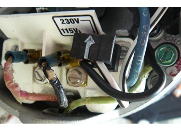
Pool pumps are wired to run on either 230V or 115V. Most are run on 230V and are preset at the manufacturers at 230V. If you are going to wire your own pool pump, you must first know what voltage is coming to your pump from the house circuit breaker. Also you must ensure that the electrical supply agrees with the motor's voltage, phase, and cycle and that all electrical wiring conforms to local codes and NEC regulations. If you are unsure of this voltage or are unfamiliar with electrical codes and regulations, have a professional electrician wire your pump for you or at least check your work.
Failure to wire the pump correctly can cause electrical shock or can damage your pump motor and void your warranty.


Larry Posted: 1/8/2013
Steps 6 & 7 of your instructions have the red wire connected to L1, and the black to L2. This is the reverse of convention, as I understand, and all the web sites I find that discuss L1 & L2 and their colors.Reply
InyoPools Product Specialist Dennis R. Posted: 11/25/2012
Shawn - Sounds like you may have 120V coming into your motor that is probably set up for 230V. Check your source voltage with a meter and see if it's 120V. If so, you will have to reconfigure your motor to 120V. New motors are set and shipped at 230V.Reply
Shawn Posted: 11/25/2012
My Hayward pump stopped working after 6 yers so I replaced it. The new one just hums like the original and gets hot. Red to L1, black to L2, green to ground. Any suggestions? ThanksReply
InyoPools Product Specialist Dennis R. Posted: 11/6/2012
ghayden - Make sure your DE filter is clean. Besides backwashing you should pull all the grids and wash them individually. If that doesn't bring the pressure down, you might consider buying a larger filter.Reply
ghayden Posted: 11/5/2012
My old 3/4 hp SwimQuip pool pump (25+ yrs) needed to be replaced. When I replaced it, I saw that it was wired for 220V, even tho the supply is only 115V. I wired the Hayward 3/4hp replacement as a 115V pump. The pump runs fine, but now the pressure on my DE filter is doubled and I am afraid the elements won't take the stress. Where do I go from here?Reply
InyoPools Product Specialist Dennis R. Posted: 10/2/2012
115V motor wiring - It sounds like your motor is configured for 230V and you are supplying 115V. Most motors come from the factory set for 230V operation. If your source power is 115V, you will have to reconfigure your motor to run on 115V.Reply
Anonymous Posted: 9/30/2012
I have a grey wire, white wire and a copper wire. When I turn the pump on, it runs for five second. Then trips a breaker. The grey wire is connected to L1 and the white wire is connected to L2. The copper wire is connected to the housing. 115 voltsI replaced the motor on a dura-glass pump.
Reply
InyoPools Product Specialist Dennis R. Posted: 9/26/2012
matt - This is AC power so the motor is run with the wires connected to either terminal. Sometimes on 115 volt motors, there will be a designation as to where the "hot" lead goes. This is done so that the hot lead is connected to the side of the circuit that has the overload closest to that terminal.Reply
matt Posted: 9/25/2012
If the L1 and L2 wires are reversed will the pool pump still run?Reply
Anonymous Posted: 8/26/2012
great info . thanksReply
InyoPools Product Specialist Dennis R. Posted: 8/24/2012
TAMMY - Sounds like a major wiring problem. You're going to have to have an electrician look at this one.Reply
InyoPools Product Specialist Dennis R. Posted: 8/24/2012
Tony - You may have a capacitor problem. See our guide on replacing capacitors. If that isn't the problems, you may have to have an electrician look at your wiring.Reply
TAMMY Posted: 8/23/2012
WE HAD SOME SERIOUS ISSUES GOING ON WITH OUR HOT TUB1ST OFF THE PUMP WAS LEAKING WHEN IT WAS ON HIGH POWER
AFTER CHANGING THE PUMP THE HOT TUB GOES ON TO LOW , THE LIGHT COMES ON, THE HEAT GOES ON & THEN WHEN YOU WANT TO USE THE HIGH PUMP - IT TRIPPS THE WHOLE CIRCUIT FROM THE CIRCUIT PANEL IN THE BASEMENT- GOES PASS THE GHFI PLUG INSTALLED ON THE SIDE OF THE TUB. 2 SPEED 110V 11.5 HP- NEW CIRCUIT BOARD, NEW TERMINALS, NEW PLUG WHAT'S HAPPENING?????
Reply
Tony Posted: 8/22/2012
When I turn my pump on, it sounds like it is switching on and off. I have it wired in the 115V configuration.Reply
InyoPools Product Specialist Dennis R. Posted: 8/22/2012
Daniel - For 220V wiring with red and black wires hot and green ground, red to green or black to green should be 110 on a 220 volt circuit. It would be 220 across red and black. A note: If one of your lines has been burned out say after a storm, you can still see 110 across EACH of the separate lines but you will have a 0 reading across the red and black lines.Reply
Daniel Posted: 8/21/2012
So back to someone else's question. Is each leg suppose read 120 v individually, or 230v individually?Reply
Bob Posted: 8/11/2012
I am installing a 1-1/2 hp pump for an above ground pool. Operating voltage is 230,8.7A, 12 ga wire, approx 100 feet from source, L1 and L2 only. I have purchased a 20 amp GFCI breaker. According to the instructions it states 'do not ground neutral on load side of breaker.' Since the motor frame must be grounded to a ground rod and the pool, do I leave the load side neutral disconnected? If so, will the GFCI work properly?Reply
InyoPools Product Specialist Dennis R. Posted: 8/8/2012
djbinva - If you put the meter probes on the red and black leads, it will read around 230V if your source power is 230V.Reply
djbinva Posted: 8/7/2012
What voltage will the black or red line be in a 230V setup? Are they each ~115V when measured(ie 230V combined) or should they each read 230V?Reply
InyoPools Product Specialist Dennis R. Posted: 7/31/2012
Bill - According to the motor manufacturers, there is no difference in efficiency between 230 and 115 if the proper voltage is available. The only savings might be in the wire size to the pump. Wire is rated according to its ability to carry current (amps). Since 230V runs with half the amperage of 115V, the required cable to the pump would be smaller and less expensive.Reply
Bill Posted: 7/31/2012
I have a pool pump that was wired for 115 volts by an electrician. The pool service said it should have been wired at 230 because it will last longer and run more efficiently and use less electric. It can be run either way. Which is correct?Thanks,
Bill
Reply
InyoPools Product Specialist Dennis R. Posted: 7/22/2012
Dan - 1- If you are looking for a 30 amp GFCI, I am assuming that your pump is wired for 115V. If you pump is wired for 230V, you need a 15 amp GFCI. I checked with the local hardware stores and as you said, they do not carry 30 amp GFCIs. They recommended going to an electrical supply house. 2- A switch is more convenient but pulling the plug works.Reply
Dan Posted: 7/21/2012
I have 2 questions. 1- The manual for the pump which is a hayward 1.5 hp superpump. Using a rubber cord and plug to an outlet near the pump. Manual says needs a 30 amp breaker and 10 awg wire. How do you GFCI a 30 amp pump? I cannot find a 30 amp GFCI recepticle or a 30 amp GFCI breaker. 2- does it require a disconnecting means such as a switch?Reply
InyoPools Product Specialist Dennis R. Posted: 7/7/2012
Bill - Yes you can use the bare wire for ground.Reply
InyoPools Product Specialist Dennis R. Posted: 7/7/2012
tonito - When an in ground pool is installed, a grid of metal rebar is laid down in and around it and all electrical equipment (lights, pumps, heater) is grounded to it. See step 17 in How To Build an In-ground Pool. If your pump was stolen, you should see a heavy copper wire coming out of the ground where the pump was.Reply
Drbeatle Posted: 7/5/2012
thank you so much,I was told my pump was burned out but it was just the capacitornow i have a spare pump motor because the pool company replaced it under warranty
Reply
Bill Posted: 7/4/2012
The wire to my timer and pump are black, white, and bare. Can I use the bare as the ground or do I need to buy wire with the green ground?Reply
tonito Posted: 7/3/2012
Well i want to thank the guys with the pictures and instructions i just needed help with tje last picture i dont understand what bonded means or how to connect that wire so if i can get the help i will apreciated im berly starting to lwarn in how to install it for aome bad reason they stole my pool pumpsReply
swil33 Posted: 7/2/2012
I have a AO Smith B855 motor and have four wires going to pump (Red, Blk, Grn & White). My motor is two speed (Hi/Lo) and 230V (115 x 2) and the lugs on motor are labeled B, L1, L2 & A. My question is how should it be wired? only the Hi speed runs when I have it wired like B-Wht, L1- Red, L2-Blk & nothing on B.Reply
InyoPools Product Specialist Dennis R. Posted: 6/26/2012
SJBURKS - The Salt Chlorine Generator is connected to the same timer that controls your pump. See our How To Guide on installing a Salt Chlorine Generator: http://www.inyopools.com/HowToPage/how_to_install_an_in_line_salt_chlorine_generator.aspxReply
SJBURKS Posted: 6/25/2012
How can I wire my salt unit so that it runs with the pump?Reply
Anonymous Posted: 6/17/2012
Would like to thank the poster of this, the motor I got showed (wired for 230 from factory) guess what, the jumper was in the wrong position! This was the only place that had a picture of it in the correct position for 230!Reply
InyoPools Product Specialist Dennis R. Posted: 6/14/2012
kc - Yes, you can use a 1 HP motor with the pump housing that came with the original 2 HP motor. However, you will also have to buy a new impeller and possibly new diffuser that match up with a 1 HP motor.Reply
kc Posted: 6/12/2012
Can one use a 1 hp (1 and 1/6 hp ) super pump on a 2 hp model 2615 pump impeller/strainer housing still new in the box which was given to me. I know the inlets are 2 inch but I plan to use a 2 inch to 1 and 1/2 in reducer to match my 1 and 1/2 inch pool lines.Any problems that might arise using this combo?
Reply
InyoPools Product Specialist Dennis R. Posted: 6/11/2012
Beth - Motors can get very hot - almost too hot to touch - especially if the sun is beating down on them on a hot day. A couple of things to check. Make sure to clear any debris away from the base of the motor. Check your line voltage to make sure it's within 10% of 115V or 220V. In some areas it will drop with heavy load. If your pump is far from the breaker box, you may have to look at increasing the wire size to the pump. Also check that the impeller is not clogged with debris. Your pump may be working harder than it has too.Reply
Beth Posted: 6/9/2012
I just replaced my pool pump motor. Motor seems to get very hot in a short period of time. How warm or hot should the pump motor get? And at what point would the pump motor shut down?Reply
Anonymous Posted: 6/9/2012
Thanks so much for info...youz guyz are zee bestReply
InyoPools Product Specialist Dennis R. Posted: 6/9/2012
2 red wires - No it does not matter which red wire goes to L1 which goes to L2. They are interchangeable. What is important is to make sure that your pump is set up correctly for the power coming in. If you have 220V from the breaker box, your pump has to be configured for 220V. If 115V, pump must be configured for 115V.Reply
Anonymous Posted: 6/8/2012
Let me clarify this...tore out my old 1 hp ao smith and replacing it with a 1 hp hayward super pump. 2 red wires and a green from the old set up. Does it matter where the 2 reds are connected to, ie L1 or L2?Reply
InyoPools Product Specialist Dennis R. Posted: 6/7/2012
Henry - According to the motor mfr rep, it is ok to switch from one speed to the other without turning the motor off, and letting it stop. Air switches on spas change from low to high to off as they progress through the normal cycle. Some pump motors actually start on low speed all the time, regardless of which speed is selected. This reduces the inrush current.Reply