How To Wire A Pool Pump

WRITTEN BY: 

  3.42 out of 5 stars on 126 ratings
(Click on a star to add your rating)

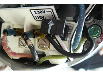
Pool pumps are wired to run on either 230V or 115V. Most are run on 230V and are preset at the manufacturers at 230V. If you are going to wire your own pool pump, you must first know what voltage is coming to your pump from the house circuit breaker. Also you must ensure that the electrical supply agrees with the motor's voltage, phase, and cycle and that all electrical wiring conforms to local codes and NEC regulations. If you are unsure of this voltage or are unfamiliar with electrical codes and regulations, have a professional electrician wire your pump for you or at least check your work.
Failure to wire the pump correctly can cause electrical shock or can damage your pump motor and void your warranty.

Things You'll Need

Video

Step by Step

Top

Step 1

Measure the voltage on the wires going to your pool pump. See "How To Use a Multimeter to Test a Pool Pump Motor - Voltage". This voltage will be either 230-240V or 115-120V. Pool Pump manufacturers commonly list these as 230V or 115V. Generally you will have three wires coming to your pump. For 230V you will generally have a red, a black and a green wire. The red and black wires are both hot. There is no neutral. The green wire is always ground. For 115V the three wires are generally black (hot), white (neutral) and green (ground).

Click Here to View our Available Inground Pool Pumps

Click Here to View our Available Above Ground Pool Pumps

Step 2

CAUTION: Before you start wiring your pool pump, turn off all power to the pump at the breaker box.

Step 3

Unscrew the two screws that hold the cover over the back end of the motor. Remove the cover to expose the electrical connectors.

Click Here to View our Available Inground Pool Pumps

Click Here to View our Available Above Ground Pool Pumps

Click Here to View our Available Pool Pump Motors 

Step 4

Screw a metal elbow onto your pool pump at the end of the motor.

Step 5

Run conduit from the metal box to the pump. String your three wires thru the conduit and metal elbow into the end of the motor. Screw the conduit collar onto the end of the elbow. Ensure that your wire size is adequate for the HP rating and distance from the power source. Check your pool pump owners manual for the correct size. Wire sizes generally run 14 AWG for motors up to 1 HP and from 14 AWG to 10AWG for larger motors depending on HP and Voltage.

Step 6

If you are wiring for 230V, the three wires coming to the pool pump from the circuit box are red, black and green. In this example for Hayward pool pumps, red will go to the L1 terminal and black will go to the L2 terminal. The green wire will be under the green screw to the far right. In addition there is a black plug with two wires coming from inside the motor , a black wire and white wire with a black tracer line. The black plug is positioned so that the white arrow on top of the 2 prong black plug is pointing at 230V.

Step 7

For clarification, this picture shows the terminals without the wires. The red wire is attached to terminal 1 of Line 1 (L1). The black wire is attached to terminal 3 of Line 2 (L2). The green wire is attached to Ground (GND). The black plug is positioned so that the black wire is attached to terminal 5. For 230V the white wire is not attached.

Step 8

If you are wiring for 115V, the three wires to the pool pump will be black, white and green. Attach the black (115 V) wire to terminal 1 of Line 1 (L1). Attach the white wire (0 V) to terminal 3 of Line 2 (L2). Attach the green wire under the Ground screw (GND). The black plug is shifted in position so the black wire is attached to terminal 4 Line 2 (L2) and the white wire is attached to terminal 5. Note: in this position the white arrow on top of the 2 prong black plug is pointing at the 115V label.

Step 9

Replace the pool pump motor cover and secure it with the two screws.

Step 10

Lastly your pool pump motor must be bonded in accordance with local electrical code requirements. Use a solid copper conductor, size 8 AWG or larger. Run this wire from from a reinforcing rod to the pressure wire connector provided on the motor housing. Note: In this example the wire coming from the bottom of the picture is going to the pump. The upper wire is going to the heater to bond the heater.

Comments

Top
(481 to 484 of 484)

Anonymous  Posted: 5/28/2011 

Thanks for the info... It's a shame Hayward couldn't write anything like this in the instruction manual that comes with the pump.
 Reply

Anonymous  Posted: 5/27/2011 

Excellent article, especially the color codes differentiation for 110/220. Had my pump up and running in 5 mins after making the adjustments. Thanks guys!
 Reply

Anonymous  Posted: 11/26/2010 

Perfect...especially the wiring part for moving the black wire so it is only on one prong for 220v. I removed this to attach the a wire and put it back on incorrectly!
 Reply

Anonymous  Posted: 10/9/2010 

These directions saved me from burning up a 200+ dollar motor! Thanks for the info.
 Reply