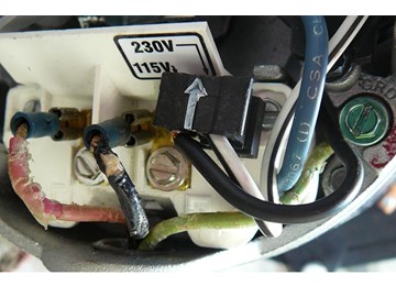
Pool pumps are wired to run on either 230V or 115V. Most are run on 230V and are preset at the manufacturers at 230V. If you are going to wire your own pool pump, you must first know what voltage is coming to your pump from the house circuit breaker. Also you must ensure that the electrical supply agrees with the motor's voltage, phase, and cycle and that all electrical wiring conforms to local codes and NEC regulations. If you are unsure of this voltage or are unfamiliar with electrical codes and regulations, have a professional electrician wire your pump for you or at least check your work.
Failure to wire the pump correctly can cause electrical shock or can damage your pump motor and void your warranty.


Mark Posted: 6/17/2020
Appreciate you making this page. step 7 made it clear. L1 and L2 and terminals...seeing those numbers made something simple very clear with a pictureReply
InyoPools Product Specialist Matt S. Posted: 9/2/2020
Glad to help. Thank you for reading!Reply
Jack Disser Posted: 5/23/2020
i have a new 2HP INGROUND POOL PUMP 5850GPH DUAL VOLTAAGE MOTOR WITH DAMAGE THE WIRING DOES NOT LOOK LIKE YOUR PICTURES , I HAVE 30 amp Service ,Reply
InyoPools Product Specialist Matt S. Posted: 10/23/2020
What is the part, model, or catalog number on your motor's label? A picture of the motor label would be most helpful.Reply
Steve Posted: 3/25/2020
Similar question about wiring hayward pump for 230. Exisiting setup has 2 blue wires and green for ground. Is it correct that either blue wire can be connected to either terminal. TksReply
InyoPools Product Specialist Matt S. Posted: 3/31/2020
If you are wiring for 230, and have two hot lines, and one green; no matter the color of the wire, one hot line goes to one terminal and repeat for the other terminalReply
keith Posted: 1/11/2020
I have two black wires one from "load out" and the other is to" line in"which one gore to L1?Reply
InyoPools Product Specialist Matt S. Posted: 1/13/2020
Are you wiring for 120 or 240?Reply
Redmisto Posted: 1/15/2020
I have the same situation - Two black wires and a ground wire. Hooking up a 230 variable speed motor - ECM16SQU.Reply
InyoPools Product Specialist Matt S. Posted: 1/17/2020
Because it is 230 volts, both lines are carrying 115 volts; so it does not matter which line goes to which terminal. One black wire goes to L1; the other black wire goes to L2. There is no wrong answer.The green ground wire goes to the green screw adjacent to the L1 and L2.Reply
Chuck Grimm Posted: 6/25/2019
Hello I have a Pentair Clean and clear 150 with a AO Smith motor… My switch burned up, I replaced it and need a diagram to re plug the wires back in… Need three from power and the ones going to the white panel… Please help I’ve been working on this for days Thanks ChuckReply
InyoPools Product Specialist Matt S. Posted: 7/9/2019
The Clean and clear is a filter, but the motor is mounted to the pump housing. If you need a wiring diagram for a specific motor we would need the part or catalog number of the motor.Reply
Rob Posted: 5/29/2019
I have watched your video and another YouTube video about connecting a 115V pool motor. Your video says the white wire is L1 and the black is L2 the other video is the exact opposite. Does it matter?Reply
InyoPools Product Specialist Matt S. Posted: 5/30/2019
On the side of every pool pump motor, there is a wiring diagram for that specific model. Follow the wiring guidelines listed on that tag.Reply
Scott T Posted: 5/17/2019
I have a new Century AO Smith SQ1102 pump for my pool.... installation has been pretty straightforward except that the input power terminals are not labeled L1 and L2. With my red and blue power wires (230v), is there polarity with respect to the terminals? I don't want accidentally run the pump in reverse, you know?Reply
InyoPools Product Specialist Robert M. Posted: 5/17/2019
Hello Scott - There is no polarity. It will not run in reverse.Reply
Scott T DeSanti Posted: 5/17/2019
OUTSTANDING!Reply
Anonymous Posted: 4/23/2019
This video was very helpful. Thank you. Also, I am a customer that order parts from your co. I am awaiting for an Impeller.Reply
skip Posted: 3/30/2019
Can you change out a 110 V in to a 220V Yes or NoReply
InyoPools Product Specialist Matt S. Posted: 4/1/2019
I need you to clarify your question because it is a little vague. Are you trying to wire a 115-volt motor so that it accepts 230 volts? Or are you trying to switch a dual voltage motor from 115 to 230? Or are you wanting to change out a 115 motor for a whole new 230 motor?Reply
tom Posted: 1/17/2019
I have seen on several videos some impellers have a wear ring and some don't. If mine does not have a wear ring but the impeller keeps falling out can I put one on to hold impeller in place when trying to reconnect motor into housing?Reply
InyoPools Product Specialist Robert M. Posted: 1/17/2019
Hello Tom - What is the make and model of your pump?Reply
Timothy Hendren Posted: 11/21/2018
My pump has the L1/2 and L3/4 but no black plug connection I've wired the red to L1 and black to L2 and the green to ground on a astral pump is that ok?Reply
InyoPools Product Specialist Matt S. Posted: 11/27/2018
Hello Timothy - to determine if that is the right set up, we would need to know the model or part or catalog number of the motor's tag. Can you provide that info? You can also refer to the wiring guide on the side of the motor for wiring guidance.Reply
Matthew Posted: 9/18/2018
Hello Dan - yes that wiring explanation is correct.Reply
Dan Posted: 9/17/2018
Hello, I'm conforming my connections. From my panel/timer I have dbl pole breaker. Line 1 has 120v Line 2 has 120v then I have ground. I assume Load 1 120v goes to L1 and Load 2 120v goes to L2 and Green to GND. Both the Load wires are RED GND is Green. Does this sound correct to you? Thanks for your help.Reply
InyoPools Posted: 9/5/2018
Hello David - Two speed pumps are not dual voltage. If your motor label says 230v, you can't test it on 110v. If the motor is 110v, you can run the hot line (usually black) to the low or high speed terminal, the neutral line (usually white) to the common terminal, and the ground line to the ground terminal (green screw).Reply
David Leath Posted: 9/3/2018
I have an old pump that I'm trying to wire up to see if it works. I have 4 wires coming out of the motor. How would I wire it up just to see if it's still good? The four wires are red, blue, white, and black. How would I wire it to a 110 electrical cord to see if it works? Any suggestions would be appreciated.Reply
VG Posted: 7/27/2018
Thanks for helping pool owners. I have bought a kit to rebuild my pentair whispro pool pump motor. A small pressure wire connector provided on the motor housing on back of my motor is broken. Can I just tangle the wire to the broken piece.Reply
Inyopools Posted: 5/30/2018
Wiring the way you stated will not impact the rotation or prevent tripping of the GFCI. However, the 115 diagrams on most of the motors have the neutral (white) going to L2 and the hot (black) going to L1. I would wire the way it is stated on the wiring diagram.Reply
Brent Posted: 5/30/2018
Reinstalling a Hayward 115v super pump from winterization by previous owner. Your article says that WHITE goes to L1 on a 115v installation, and black to L2. My Hayward motor shows LINE to L1. Will WHITE to L1 affect rotation direction or prevent tripping of GFCI?Reply
Inyopools Posted: 4/24/2018
Hello Matt - The 115 diagrams on most of the motors have the neutral (white) going to L2 and the hot (black) going to L1. Honestly, it will work either way.Reply
Matt Posted: 4/23/2018
Hi there, Thanks for the great site, it really helped me when I was trying to wire my new pool pump for 115v. I was wondering if you were able to check my wiring. I'm new to this so please excuse any stupid questions. I purchased the hayward inground super pump 1 HP (SP2607X10A ) I follow your steps to wire it for 115v but the diagram on the pump had the white wire on L1 terminal 2.. does this matter? If you could take a look at the link below, I would really appreciate it. Thanks in advance for the help. Great Site!! Link to photos https://drive.google.com/drive/folders/1ir1Oq9fcCI2u0HiaJzHMmFFJEbpImdxp?usp=sharingReply
Inyopools Posted: 4/16/2018
Hello Jake - A 2-speed motor requires four wires; high speed, low speed, common, and ground. The colors may be differ on different installations. You'll need to look at the label on the motor to see what line goes where and then match those lines to your timer or control box.Reply
Jake Posted: 4/13/2018
Hello. Great diagrams but my pump has two black, one red, and the green ground coming in to it. What do I do with the "extra" black wire?Reply
Inyopools Posted: 11/13/2017
alex - You wiring sounds correct. To extend your bonding wire to your pump housing, use a copper split bolt (at any h/w store). See Step 23 of our guide on "How to Install a Hayward Aqua Rite Salt Chlorine Generator" for an example of what this bolt looks like and how it is used.Reply
alex Posted: 11/10/2017
I just got my new motor back.I have 3 wires blue, red, and green an I connected the wires to the motor. I connected the blue to l1 and red to l2 is that correct. My bonded wire doesn't reach the motor housing.Reply
Inyopools Posted: 10/22/2017
Kevin - The underground wire that was attached to the heat pump should be sufficient to bond the pump to the grid. But you might also attach the wire to a steel pipe pounded in the ground as a precaution, since you can't be sure if the underground wire is attached to the grid.Reply
Kevin Posted: 10/19/2017
So that's the thing. have found all grid wires to vacant heat pump. One coming from underground and one that came from pool motor. I have connected other grid wires coming from underground and lanai frame to the pool motor. I still have wire that used to attach to motor and another that runs underground. Do I need to secure the wires to a steel rod pounded into the earth?Reply
Inyopools Posted: 10/19/2017
Kevin - Most pools have an electrical grid that all electrical equipment can tie to so everything is operating on a common base. See Steps 7, 8 and 17 of our guide on "How To Build an In-Ground Pool". See if you can find the bonding wire that should have come from the grid to your heater. If you don't have access to this grid, you should at least connect the pump to a steel rod driven into the ground as you suggest.Reply