Pool pumps are wired to run on either 230V or 115V. Most are run on 230V and are preset at the manufacturers at 230V. If you are going to wire your own pool pump, you must first know what voltage is coming to your pump from the house circuit breaker. Also you must ensure that the electrical supply agrees with the motor's voltage, phase, and cycle and that all electrical wiring conforms to local codes and NEC regulations. If you are unsure of this voltage or are unfamiliar with electrical codes and regulations, have a professional electrician wire your pump for you or at least check your work.
Failure to wire the pump correctly can cause electrical shock or can damage your pump motor and void your warranty.


Erik Posted: 8/10/2019
And on a 110 we’re do they go?Reply
InyoPools Product Specialist Matt S. Posted: 8/14/2019
Refer to step 8.Reply
scosta5 Posted: 7/28/2016
I have a question maybe 2, i just bought a 3 hp pump to run the water falls and was told to install a 220 for the pump. i have installed a 30 amp breaker and used red and black on the breaker, white nutural and copper to ground. My question is my pump says to use only red and black and ground, where does the white go to? Also if i decided to put in a 20amp or 30 amp switch before the pump what wires do i use? do i still need the whit at the switch. Pleaae someone helpThanks
Reply
InyoPools Product Specialist Dennis R. Posted: 7/16/2016
CLIFF - Don't know anything about this motor's internal wiring to convert to 115V but it sounds like you have that covered. As to the supply line for 115V, white goes to L1 and black goes to L2.Reply
CLIFF Posted: 7/14/2016
MY JACUSSI CAME SET FOR 230V. NOW TO CHANGE TO 115V IT SAYS ON THE MOTOR TO SWOP THE WHITE WIRE ON B OR L1 WITH THE BROWN WIRE B OR L2. EASY ENOUGH TO DO. IT'S 15 YRS. OLD WITH NO SELECTOR SWITCH. THEY SAY NOYHING OF WHERE THE 115 ELECTRIC COMING IN, WHERE IT SHOULD BE ATTACHED.UNDER L1 THERE ARE A RED AND ORANGE WIRE ON THE SAME CONNECTOR WITH A YELLOW WITH BLACK LINES ON IT UNDER L1,BROWN. THE ONLY THING UNDER L2 WHITE WIRE IS A YELLOW CONNECTOR. I DID HAVE SMOKE FOR 1 MINUTE ON A TRIAL RUN. NOT SURE ABOUT THE RUSTY CAPACITOR. I THINK I WILL JUST REPLACE IT. THERE IS SOME HUM WHEN I TRY WHAT I THINK IT SHOULD BE. I'M READY TO THROW IT AWAY, BUT I DON'T HAVE A LOT OF MONEY. ANY SUGGESTIONS ?Reply
InyoPools Product Specialist Dennis R. Posted: 7/11/2016
Cal - Our motor manufacturer technical reps advise us that this should be okay.Reply
Cal Posted: 7/8/2016
Hi there, anybody who is an expert. My electrical system is a UK style system. It meters to 230v on one wire and 0v on the second wire. I just want to make sure that a standard pump is ok with that instead of the 115v to 115v offset. I'm thinking the pump motor wouldn't care, it just wants the correct 230v difference, but there may be something that I'm not aware of. Thanks, in advance, for any brilliance that is sure to comeReply
InyoPools Product Specialist Dennis R. Posted: 6/24/2016
Chad - The pump in your pool system must be both grounded and bonded. Grounding is accomplished with the green or bare wire that comes in with your power wires and is connected at the back of the motor under the electrical cover. This wire grounds your pump back to the circuit in the breaker box. The pump must also be bonded to the rebar grid that surrounds your pool and to which all your electrical pool units are connected - lights, heater etc. This is the wire that connects to the outside of the motor on a lug. See our guide on "How To Build an In-Ground Pool" steps 7, 8, and 17.Reply
Chad Posted: 6/24/2016
I went to my pump yesterday and found the pool cage (enclosure) ground wire sticking up in the air very close the ground connection of the pool pump. Upon further inspection, I discovered that the screw to the ground at the back of the pool pump was loose and the blue, pump ground wire was barely in the pump ground connection hole but not tightened (as mentioned above).I did A LOT of searches on how enclosures are grounded, I but can't find anything that answers my question. Should the pool enclosure wire also be affixed to the back of the pool pump along with the blue pool pump ground wire? If any layman were to look at the half-screwed, pump ground terminal, the blue, pump ground wire barely in the hole, and the loose, green, enclosure ground wire (cut/spliced perfectly to reach the terminal) sticking stiffly up in the about 8 inches away, they would correctly guess that it was and should be affixed to the pump ground terminal.
Stupid question with an obvious answer but better safe than sorry. Thanks so much in advance for reading and responding!
Reply
InyoPools Product Specialist Dennis R. Posted: 6/1/2016
Bubbles - I would think that you could take the hot wire from each of the breakers to produce 220V but I don't know the codes. How would you turn them off together? I would have a qualified electrician answer this question.Reply
InyoPools Product Specialist Dennis R. Posted: 6/1/2016
timer wiring - I would have an electrician look at your wiring. Timers are sold for 220V or 110V. Unless there is a wiring trick that I don't know about, 220v has to come out of a 220 timer.Reply
InyoPools Product Specialist Dennis R. Posted: 5/31/2016
MarkL - I think you are good. To clarify: the two wires coming off the breaker each should show 110V when each is measured against ground. When you measure across the two wires, they will show 220V. At the motor, a probe at L1 and one at L2 will show 220V.Reply
Bubbles Posted: 5/31/2016
If you have the switch to the outside, and pool timer that is a 220 , but the circuit breakers are separate for each, and the old pump was set at 220 can those 2 110 circuit b reakers b e going through timer to make the total of 22oReply
Anonymous Posted: 5/31/2016
Here is my odd trouble I have a 220 timer the hayward motor befor re this new one was wire 220, the timer is wired for 220 and the switch to turn things on and off outside that is separate ftom tmer timer stopped working years ago. Now put new 220 timer in, put new motor in didnt change switch, power showing to the 220 time with gage rely shows xv 110, look in circuit box and it is a 1 pole breaker says but under it might be breaker for switch. Since timer was always wired for 220 and other motor was wired for 220 what do I do now I am told that my friend used circuit b reaker to timer to turn pump on and off . Any thoughts. Can a 220 timer thatt is correctly wired be used for a 110 m No torReply
InyoPools Product Specialist Dennis R. Posted: 5/30/2016
Cbar – Yes, you can attach your two black wires to the two white wires extruding from the end cap. I would put a conduit around the white wires and connect them in an electrical box. I assume the black wires are supplying 220V.Reply
MarkL Posted: 5/30/2016
My supply is 220v (Thailand). My pool pump is a Hayward Tristar 220v. I have wired the pump via a two pole 16A breaker and two pole switch to the pump. One 220v wire goes to L1 and the second to L2. The pump is grounded.Is this correct?
Any help appreciated.
Reply
cbar Posted: 5/25/2016
About to install new 1 1/2 hp Hayward pump replacing a 1hp flotec. New pump is set for 230. Two white wires were already attached to motor and extruded from end cap. My conduit has two black wires and a green wire. Can I attach my to black wires to the white wires? I'll ground the green..Reply
caly Posted: 5/24/2016
Found your company on line (thank god) .Very helpful and great prices for good stuff .Will use again ,your videos are very helpful .5 stars all the way.
Reply
InyoPools Product Specialist Dennis R. Posted: 5/23/2016
JSL - When you measured the voltage coming into the pump, did you measure it across the two leads and not one lead to ground and the other lead to ground.If you have 230V coming in, it will show 230V across both leads and 115V from each lead to ground. From you description, it sounds like you have 230V coming in otherwise it would not run at all. Low pressure could be due to a number of problems. See our guide on "How to Correct Low Water Pressure in Your Pool System".Reply
JSL Posted: 5/22/2016
Had to replace my pool pump. Pump was preset to 230V. Measured voltage at wires coming to the pump at 120V. Changed pump selector to 115V setting, it runs for about 3 seconds and then trips the breaker. If I switch the pump back to 230V setting the pump will run but is not creating much pressure and/or suction. What am I missing?Reply
InyoPools Product Specialist Dennis R. Posted: 4/30/2016
chipwad - From your description, it sounds like you wired the pump correctly and that the problem is in the pre-wiring of the black plug. According to the manf motor engineers, the motor should not be used. The wires should be switched, black on left and white stripe on rignt, or the motor should be replaced. If you bought the pump from us, give our service reps a call to see what we can do. Try to talk to Rob or Alex.Reply
chipwad Posted: 4/28/2016
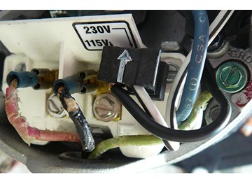
Just installed my new Jacuzzi Magnum 1hp pump. I'm replacing the old one that lasted 17 years till it smoked last week. My system is wired for 230v, I have 2 black wires (hot) and 1 green. Everything I read, and also observed, that the pump came pre-wired for 230, so I did not touch the jumper. The white arrow on the jumper is pointing to 230v. When I closed the circuit breaker to test it, and prime the pump, it made a loud hum sound and then tripped off internally. I did see a little smoke.I measure 230v with the black wires both connected and disconnected, so input power does not appear to be the problem. I went back to your instructions for wiring a pool pump. The picture in step six is from a Haywood pump, but the layout looks identical to mine. The power wires connecting to the L1(terminal no.1) and L2(terminal no.3) and the jumper aligned with the arrow points to 230v. Again from the picture, with the jumper set for 230v, It shows the jumpers black wire connected to terminal no.5 and the jumpers white wire not connected.
I have now discovered, this is not how my pump came pre-wired. On mine, with the black plug’s arrow pointing at 230v, the plug’s white wire is connected to terminal no.5 and the black wire is not connected.
Is this my problem and where do we go from here?
I have pictures if you would like visual confirmation.
Reply
InyoPools Product Specialist Dennis R. Posted: 4/22/2016
DYI guy - I've been told by electricians that pool equipment has to be both grounded (ground wire back to the power source) and bounded (heavy wire connected a grounded wire grid to all pool equipment). Both are required to reduce electrical surges to equipment and people.Reply
DYI guy Posted: 4/20/2016
I have a question, when wiring something 220V we used to use a 10-3 W/grd(white, black, red,green).in wiring a pump motor the pool company put in a 10-2 w/grd (White, black, green) Isn't running a wire to the chassis of the pump almost equivalent to an equipment ground? and not really using the bare wire as a neutral?
Reply
InyoPools Product Specialist Dennis R. Posted: 4/18/2016
Kevin - Either black wire can go to L1 or L2. The green wire, of course, has to go to the green grounding screw.Reply
InyoPools Product Specialist Dennis R. Posted: 4/18/2016
PLEASE ASSIST - I'm not sure what they did here. If they replaced the whole light fixture, it comes already attached (and sealed) with enough wire to reach the junction box at the house. People don't generally rewire the light at the pool because of the risk of not adequately sealing the fixture when the wire comes in. In any case, it doesn't make sense to connect the earth (green) wire to the neutral (white) wire. Sounds like the light is left ungrounded.Reply
Kevin Posted: 4/17/2016
Question: just bought a Pentair Whisperflo single speed pump/motor to replace similar one. my wiring to the old/new pump is two black wires and a greem. Does it matter which one is L1 and L2? One is black with white lettering, the other is black with no lettering. ThanksReply
PLEASE ASSIST Posted: 4/17/2016
I need assistance please. While not at home, my wife and son replaced the light in the swimming pool. They connected the earth and neutral wires together at the immersed pool light. Apparently they said there was no place to connect the earth wire. Is that acceptable?. Please assist.Reply
InyoPools Product Specialist Dennis R. Posted: 3/18/2016
Newbie - I think you mean in parallel rather than in series and that would be all right. If you have a timer, it would be the same as wiring both sets of input wires from the pump to the output terminals of the timer. Make sure the circuit breaker is large enough to handle the amps for both pumps.Reply
Newbie Posted: 3/17/2016
Since the cleaner pump needs the filter pump to work correctly, I was going to series the filter and cleaner pumps together but I wanted to double check if that should be the correct way to do it.Anyone has any suggestion or see a problem with wiring the cleaner and filter pumps in series directly to main house breaker (240VAC)?
Reply
InyoPools Product Specialist Dennis R. Posted: 2/6/2016
pdf – Sounds like a timer issue. Look at steps 8, 9, and 16 on our guide for "How To Install an In-Line Salt Chlorine Generator". It's specifically for installing a SCG but the voltage measurement and power hookup are the same for a pump motor. The output lines on the timer are actually going to both the SCG and the pump. Make sure you have a timer for 220 volts. It's different from a 110V timer.Reply
pdf Posted: 2/5/2016
Bought a new century HST110 1 hp motor, connected lines to L1 and L2 green to ground. Plug is set in motor for 230V turned timer to manual and nothing. Checked voltage at motor terminals and its 120 for each terminal. Bad timer? at one point there was no voltage on one leg coming off the timer, but there is now and still not running. took motor to inside and hooked up to 220V direct from breaker box and it ran.Reply
InyoPools Product Specialist Dennis R. Posted: 1/12/2016
KMH - I not sure how your pump is wired. If initially you measured 230V across the two black lines at the supply side, you should see 230V across the same two black lines that are screwed into L1 and L2 - not 0V. I assume there is nothing between the supply lookup and the pump terminals. If you did have 230V across L1 and L2 and your configuration switch was set at 240 and your pump did nothing, I would say that something was wrong with the wiring inside the pump.Reply
KMH Posted: 1/10/2016
The model UST1072 - A.O. Smith Round Flange 3/4 HP Up Rate Motor.Measured the voltage on the wires going to the pool pump. The voltage is 230V. There are three wires coming to the pump, two blacks and one green.
Connected one black wire to the L1 terminal and the other black to the L2 terminal (both under the screw). The green wire connected under the green screw. Kept the switch at 230V position. Turned on the pump but nothing happened! No rotation no humming! Measured the voltage L1 to ground it was ~130V, L2 to ground ~130V but L1 to L2 ~0V. Another user (B-Rad) on 4/29/2015 has also reported exactly the same issue. Your answer was that it should measure 240V across L1 and L2. I also wired the pump for 120V and plugged it inside the house to the outlet (not the pump breaker) and the motor runs fine!
It looks like the switch at 240V position (connected to 240V voltage) is not working but the switch at 130V position (connected to 120V voltage) works fine. What now?
Reply
InyoPools Product Specialist Dennis R. Posted: 11/8/2015
Tominboston - I don't know how strict the codes are in your area but most people would just use the same lines coming to the pump. Anyone working on the electrical system should know enough to shut the power off before working on the line and they should have enough electrical knowledge to know that the pump is wired for 220V and that the white line is hot during operation. Some people tag the white wire with red tape as an extra precaution.Reply
Tominboston Posted: 11/7/2015
I would like to replace my single speed 115v pool pump with a variable speed 230v. I have fairly large conductors coming out to the pump now, green, black, and white. I live in MA, am I allowed to reuse these conductors and wire to a 230v breaker ? I was wondering if it was possible to put some color coded electrical tape around the conductors to signify it is a 230v circuit. Or do I need to pull the politically correct color conductors out to the pump? It's about a 100 ft run, so it's not trivial. But I want to do what is right. Thank you for any advice. I assume the existing conductors are more than adequate to handle half the current they do now at 115v, it's just the color code I am concerned about.Tom
Reply
InyoPools Product Specialist Dennis R. Posted: 9/25/2015
tatum4hire – The max load rating on your pump is 18.6 which is close enough to trip your 20 amp breaker if you have other issues. You might check the size of your wire between the circuit breaker and the pump. See “Recommended Wire Size”. Also check that your motor is getting enough ventilation and that the debris around the bottom of the pump is cleared out. Other than that, if you have 220 available, I would go to that voltage to reduce current. Remember to change the motor voltage setting to 220V.Reply
tatum4hire Posted: 9/24/2015
I recently moved into an older home and I have a AO SMITH ST 1102 pump on my pool. It is currently wired to run off 115v. It is drawing close to 16 amps during operation. It commonly trips the 20 amp breaker upon startup. I have tested the start capacitor and measures 172 uF - well within the tolerance. I have replaced the 20 amp breaker and it does not help. I am considering that there must be a surge current tripping the breaker. I have 230V available at the sub panel. Should I just switch to 230V and drop the operating current?Reply
InyoPools Product Specialist Dennis R. Posted: 8/28/2015
Chris- Yes, you cannot wire a 115V only pump to a 230V circuit. It will fry the motor. Either tap off 115V off of the supply power or buy a 230V pump.Reply
Chris Posted: 8/27/2015
Hi, I just bought an AO Smith BN50V pump. I have 230v outlet coming of the breaker. I just noticed the voltage rating on the BN50V is only 115V. Will I ruin this pump if it's connected to a 230V outlet?Reply