Pool pumps are wired to run on either 230V or 115V. Most are run on 230V and are preset at the manufacturers at 230V. If you are going to wire your own pool pump, you must first know what voltage is coming to your pump from the house circuit breaker. Also you must ensure that the electrical supply agrees with the motor's voltage, phase, and cycle and that all electrical wiring conforms to local codes and NEC regulations. If you are unsure of this voltage or are unfamiliar with electrical codes and regulations, have a professional electrician wire your pump for you or at least check your work.
Failure to wire the pump correctly can cause electrical shock or can damage your pump motor and void your warranty.


bjohn Posted: 6/5/2013
I need a 120v receptacle by my filter it is 240v can I tap into it to get 120v? It has 2 hot and a ground.Reply
InyoPools Product Specialist Dennis R. Posted: 6/5/2013
PJ - You have to be sure what power is coming to the pump. Have someone measure it with a mutimeter. If you have 230V coming in and you configure your pump for 115V, you will fry your motor. If you have 115V coming in and your pump is set for 220V, your pump will cycle on and off. If the circuit breaker trips right after you turn the pump on, you may have the pump wired wrong.Reply
PJ Posted: 6/4/2013
My pump wires were dangling out of the pump so I disconnected the wires from the pump and replaced the water tight flex and box connector. When I finished re-connecting the wires and turned the circuit breaker on it tripped. Tried a couple of things but still no running of the pump. By reading the power requirements for my hayward T1102 1HP pump I noticed that the circuit breakers are 20 Amps and this indicates that the pump should be wired as 115 volts. However my pump switch is set to 230 volts. Is it possible that the switch was bumped while installing the wires. What will happen if I switch it to 115 volts and flip the circuit breaker on? Just trying to keep from burning anything up. Thanks.Reply
InyoPools Product Specialist Dennis R. Posted: 5/27/2013
JP - Because this is AC current, it does not matter if the black wire is attached to L1 or L2. Make sure that your supply voltage is 115V and that the motor is configured for 115V.Reply
JP Posted: 5/26/2013
Have a new hayward super pump that I want to set up on 115V. Does the black wire go on L1 or L2?Reply
InyoPools Product Specialist Dennis R. Posted: 5/26/2013
wiring - It sounds like you have four wires coming from your power supply box -black, blue, white and green. Check the voltage across a pair of wires for 230V. I would guess it's the black and blue wires. If you have 240V across black /blue, connect those wires to L1 and L2. White is extra but I would cap it off with an electrical wing nut. Green goes to the ground screw. Make sure your motor is configured for 240V.Reply
beezdotcom Posted: 5/24/2013
Thanks to user jgianoli for mentioning his problem with the spade terminals being at an angle and preventing him from easily switching from 230v to 115v...I had the same problem! Now, thankfully, I have the same solution, too.Reply
Anonymous Posted: 5/23/2013
myold trasstar had four wires black blue white and green the new super pump has only three l1 red l2 black green wire to screw. where does the white wire connect . is this the correct wiring settingsReply
InyoPools Product Specialist Dennis R. Posted: 5/22/2013
cpe.ru90 - According to the motor rep, because this is AC power, it does not matter if the black is on L2 or L1. Black and White wires can be swapped.Reply
cpe.ru90 Posted: 5/22/2013
hi, I am in the process of replacing a 115v configured super pump ust1152. while disconnecting the electrical I made note that the black was connected to L1 and the white to L2, which is opposite of what your how-to states. would the pump still work if it was wired this (incorrect) way or did I record the connections incorrectly? thanks, chrisReply
InyoPools Product Specialist Dennis R. Posted: 5/22/2013
T.I. - Unfortunately I have no information on this relay. I would suggest submitting your question to Omron directly using this contact form.Reply
T.I. Posted: 5/22/2013
I have a 2HP pool motor to be installed. How would you connect the wires back to Omron G7-2A-BUBJ-CB DC24 relay? Thanks.Reply
InyoPools Product Specialist Dennis R. Posted: 5/17/2013
fergi - Check your supply power to the motor. If it is 115V and your motor is configured for 230V, you need to change your motor's configuration to 115V. See the top of your motor label for instructions. Check your circuit breaker. For this size motor, you need a 30 amp breaker for 115V supply power or a 15 amp breaker for 230V. Also, you may have a bad breaker that needs to be replaced. Check the size of the wire to your motor. For lengths under 50 ft and this size motor, you need No.10 wire for 115V or No.14 wire for 230V. If your wire length is greater than 50 ft, you will need wire one size heavier.Reply
fergi Posted: 5/16/2013
we have installed the new 1 1/2hp hayward superpump for ingroung pool, but it keeps tripping the breaker.Reply
InyoPools Product Specialist Dennis R. Posted: 5/12/2013
rgholloman - The instructions to change the motor's configuration from 230V to 115V are often included at the top of the motor's label. The newer AO Smith motors now have a knob on the power terminal which changes the voltage easily by rotating it CCW.Reply
rgholloman Posted: 5/10/2013
the new Motor cuts off after 3-5 minutes which I understand from reading the comments that it has something to do with voltage.I have 120 volts into the pump motor. there are three wires: red, black, green. I wired it like the one I took off. red to L-1, black to L-3 and green to ground.
Inyo says that pool motors are configured to 230 volts from the manufacturer and therefore, I need to reconfigure the motor to 115-120 volts to match the voltage to the motor.
Question: how do I reconfigure the motor from 230 to 120?
Reply
InyoPools Product Specialist Dennis R. Posted: 5/5/2013
Jeremy - Sounds like you have 240V if each wire, when test separately, reads 120V. That's white to ground then black to ground. To be sure place one probe on black and one on white to check across black - white. That will probably read 240V.Reply
Jeremy Posted: 5/4/2013
Each wire has a current of 120....Both white and black. So how would I wire it.Reply
InyoPools Product Specialist Dennis R. Posted: 5/4/2013
Sid - 8G or larger solid copper wire is recommended for bonding.Reply
InyoPools Product Specialist Dennis R. Posted: 5/1/2013
Jeremy - Your supply voltage is either 240V or 120V. If the wires to your motor are your supply wires coming from the breaker box, check the voltage with a multimeter by placing the meter's probes on the white and black wires. The meter will read around 240V or 150V.Reply
Sid Posted: 5/1/2013
I have 1.5 HP pump connected @ 230 volt, 40 feet from its breaker. I have installed 3-10 G wires in 1&1/2 inch conduit which also carries 2 wires for pool lighting and 2 wires for a pool sweep pump (3/4 HP). One of these three wires is for grounding. The pumps are also grounded by a 10G copper wire to the ground slab. Should I have installed 8G grounding wire?Reply
Jeremy Posted: 4/30/2013
I bought a new Hayward super pump 1 hp. Ready to wire it and I tested my voltage and both lights lit up 240 and 120. The wires I have leading to the motor are black white and green. Just double checking on which way to wire it??? Any help would be great.Reply
InyoPools Product Specialist Dennis R. Posted: 4/21/2013
amy5674 - You are going to need a multimeter to measure the voltage on the wires. With the power on, put one meter lead on the red wire and the other on the yellow than the blue. If you measure around 220V on either pair (red/yellow or red/blue) use those two wires as your power source to L1 and L2. It does not matter which wire goes to which terminal. Be very careful not to touch these wires while you are measuring them. You are working with 240V. After you have selected the pair to use TURN THE POWER OFF, cap the extra wire with a wire connector, and hook up your motor.Reply
amy5674 Posted: 4/20/2013
I just got a Hayward RS Replacement Series Pump since the old one finally died. I have 220v...my problem is I have 4 wires coming from the box...a red, a yellow, a blue, and a green. I get the green and the red but what do I do about the yellow and the blue? Red to L1...greed to ground...and then what? ThanksReply
InyoPools Product Specialist Dennis R. Posted: 4/10/2013
Ciro – It sounds like your pool cleaner issue is low return pressure. Make sure your diverter valves are set up to open flow to the return lines in your pool – reduce flow to spa or fountains. Another suggestion – You may be building up back pressure in your return lines. One manufacturer rep suggests replacing your return nozzles with one size larger nozzles.Reply
Ciro Posted: 4/9/2013
Hi, I just purchase a Polaris 165 pressure side vacuum cleaner, How ever and connected it doesn't move and I noticed my return lines have low pressure I backed wash my filer and cleaned filter I am not sure if Im setting up the vacuum right or if its something else.Thank You
Reply
InyoPools Product Specialist Dennis R. Posted: 4/5/2013
Ciro - Yes, it is normal for a pump motor to run a little hot. Your pressure problem is after the pump. Try backwashing or cleaning your filter a couple more times to see if that helps reduce your pool's pressure level.Reply
Ciro Posted: 4/4/2013
Hi, I have a sta rite 3/4 pump 230V, my set up is 220V I have one green and two reds,is it normal that my pumps gets just a little hot? and when I first started the pump the filter gage was on 10 lbs pressure and more water pressure coming from the returning lines after 1 hr the pressure gage went up to 20 lbs and lower water pressure form returning lines.Reply
InyoPools Product Specialist Dennis R. Posted: 3/22/2013
wired for 220V - It does not matter which red wire is connected to L1 and L2. Both are hot.Reply
Anonymous Posted: 3/21/2013
I replaced my motor (wired for 220V) but I have two red wires and one green. Does it make any difference which red wire I connect to L1 and which one to L2?Reply
InyoPools Product Specialist Dennis R. Posted: 3/13/2013
Mark - You need to have three wires plus ground to connect your two speed pump to your PE153 Timer. I am currently writing a guide on How To Wire a PE153 Timer to a 2-Speed Motor which will be out in a couple of days.Reply
mark Posted: 3/8/2013
I just purchased a new 1.5 pump and a pe153 timer. I called in with my old equipment and your customer service matched up a replacement motor.i only have 1 black, 1 white and my ground.
the pump will run on what seems like low but won't run on high. any suggestions
Reply
InyoPools Product Specialist Dennis R. Posted: 3/5/2013
KateMonster - You will need someone with a voltmeter to test your voltage. Carefully connect the leads of the voltmeter to the two yellow wires. If you have 220V to the motor, it will read 220V.Reply
KateMonster Posted: 3/4/2013
I have 3 wires - 2 yellow and a green. Any idea on voltage? My pool pump is old and I'm not easily finding config details.Reply
InyoPools Product Specialist Dennis R. Posted: 3/2/2013
arb - Make sure your motor is configured for 220V. Then check the voltage on the wires. You should have 220V between the red and black wires from the supply power. Put red on L1 and Black on L2. Blue is extra but I would cap it off to be safe.Reply
arb Posted: 3/2/2013
I have 4 wires coming from the pool connection box.1-red
1-black
1-blue or gray?
1-green
my motor (A.O.Smith UST1152)..I am aware the green is ground... where do the other wires connect to the motor? thanks in advance.
Reply
jgianoli Posted: 1/14/2013
Thank you for clarifying that. My spade terminals are not sitting down as they are in pics 7&8. mine are at an angle as the top pic. so i just bent them down and connected the plug right in. Thanks again for your help.Reply
InyoPools Product Specialist Dennis R. Posted: 1/14/2013
Jgianoli - If I understand you correctly, when you convert to 120V, you will want to connect into that terminal that is "in the way". See steps 7 and 8. When you move the terminal plug over to the 115V mark, the plug will be connected to terminals 4 and 5.Reply
Jgianoli Posted: 1/13/2013
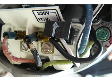
Hi, I have the 1hp hayward super pump and will be converting it to 120v.My question is when i move the plug to line the arrows up there is a spade connector that is at an angle that will be in the way, i can't bend it out of the way up as it hits the screw before getting out of the way, if i bend it down the connector will plug into this also. is this acceptable? On the first picture you can see the dual spade terminal i'mtalking about.Thanks, John
Reply
InyoPools Product Specialist Dennis R. Posted: 1/9/2013
Larry - Thanks for your comment. We do appreciate independent reviews to help keep us accurate. I did contact the experts at the motor manufacturer and they state that for 230V AC motors, either black or red wires (both hot) can be attached to either terminal lead L1 or L2.Reply