Pool pumps are wired to run on either 230V or 115V. Most are run on 230V and are preset at the manufacturers at 230V. If you are going to wire your own pool pump, you must first know what voltage is coming to your pump from the house circuit breaker. Also you must ensure that the electrical supply agrees with the motor's voltage, phase, and cycle and that all electrical wiring conforms to local codes and NEC regulations. If you are unsure of this voltage or are unfamiliar with electrical codes and regulations, have a professional electrician wire your pump for you or at least check your work.
Failure to wire the pump correctly can cause electrical shock or can damage your pump motor and void your warranty.


John Posted: 7/24/2013
My sister in law has a Hayward pump. When she plugged it in, the plug arced and melted off two of the prongs. The circuits were all checked with no problems noted. The plug was replaced and the back of the motor was checked and all seemed fine. Now when the plug is inserted into the outlet (GFCI) it immediately trips and won't start. What else could be the problem?Reply
InyoPools Product Specialist Dennis R. Posted: 7/23/2013
Dany G - According to the motor manufacturer, the neutral white wire is not needed when the motor is set up for 230V. The red and black hot wires are connected to L1 and L2 and the green wire goes to ground. Cap off the white wire with a wire nut. It is not connected to your motor.Reply
Dany G Posted: 7/22/2013
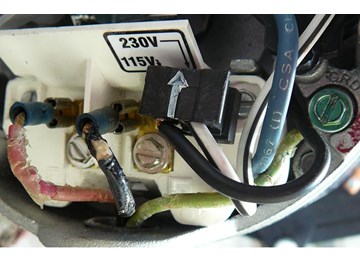
I recently purchase a new pool pump to replace my old pump which was wired for 230V. The new pump is already set for 230V wiring according to the notice posted on the pump. I look up at the picture on your web site showing how to do the wiring for a typical pump at 230V and it is the same as what I have on the new pump. However, the initial connection on my old pump was done with 4 wires (red, black, white and green for ground). I have no problem to connect both hot wires (red and black) to the L1 and L2 posts and the green wire to the green connector as indicated but where do we connect the neutral white wire that was part of the electrical connection on my old pump? I believe that the neutral white wire is needed to close the circuit but I don't know how to connect it. Can you help and clarify the situation?Reply
Brandon Posted: 7/18/2013
The motor is an A.O. Smith Century 1081/1563. The specs read as a 60hz, 2.5hp, 230v, 10.5/2.6A 3450/1725 RPM.I will see if I can determine where the white wire connects to in the motor.
Reply
InyoPools Product Specialist Dennis R. Posted: 7/18/2013
Brandon - Your problem may be with the neutral white wire. According to a motor manufacturer rep: "There is no neutral line on motors connected for 230 volts". Where is the white wire connected? On your other question, motors with 230V have half the amps of the 115V motors. I don't know the size of your motor but as an example a 2 HP motor uses 10-11 amps under full load. So your 30 amp breaker should work fine. You might check to see if it's still good.Reply
Brandon Posted: 7/18/2013
I recently bought a used hot tub with a 230V Century AO Smith Motor/heater assembly. When we wired it we set it by conventional knowledge; black and red wires as hot for the 230v, green to ground, and white to neutral. There is a 30amp GFCI breaker at the main panel. The tub came with a 50amp GFCI breaker which we wired near the pump. The voltage is correct, as we get 110 from the black and red indivudally, and 220 (240 maybe?) when both are tested together.A couple questions.
When we turn on the breaker at the panel, it immediately trips. Could this be caused by us having the white connected to neutral at the pump?
Is the second GFCI nearest the pump (the second autonomous breaker that came with the hot tub) redundant and can we eliminate it? (And/or can it be part of the problem as to why the other breaker is tripping right away?)
What size breaker do we need inside at the main panel? I have read 30, 20, 15, and the original owners told me they had a 40amp GFCI.
It has been quite frustrating with how challenging it has been finding the proper way to wire this. The AO Smith "Installation manuals" I have found online do not tell you how to wire the pump from the house.
Reply
InyoPools Product Specialist Dennis R. Posted: 7/12/2013
Florida - Wiring a two speed pump can be confusing. Take a look at our guide on "How To Wire a PE153 Digital Timer to a 2-Speed 230V Motor". It may not fit your application exactly but it does show you how the forth wire is connected. Make sure you have 230 coming out of the timer by putting the meter across black and red wires when they are both hot. Same for black and yellow.Reply
Florida Posted: 7/10/2013
I'm in the process of installing a 2 speed EE pump motor (AO Smith B2983), rated as 230V, but can't get it to turn on. I have 4 wires coming into the pump, measured with a voltage tester: green for ground, black (appears to be common) always at 115V, red at 115V when timer is in low, yellow at 115V when timer in in high. Wiring diagram on the side of motor indicates I should wire L2-common, L1-high, A-low, besides ground of course. Any suggestions or link? Thanks in advance.Reply
InyoPools Product Specialist Dennis R. Posted: 7/8/2013
WF26 wiring - Yes, L1 and L2 are interchangeable. Was your old pump set up for 230V or 115V? Can you check the voltage of the power coming to your new pump? You could have a bad pump. I'd check with the Pentair for advice before I you do much more with the pump.Reply
Anonymous Posted: 7/7/2013
Bought a new whisperflow WF26 pump set by factory as 230V. Removed old pulp adn connected the two wires to L1 and L2 and the green ground wire to the green terminal. Before plumbing into line wanted to check pump would run. Motor just hummed but not spuin. Able to freely turn motor shart. Verified the brown and white wite that are correctly set and scurely in place for 230 per label on motor. Any idea what to do. My understanding that L1 and L2 are interchangeable - is tghat correct?Reply
InyoPools Product Specialist Dennis R. Posted: 7/1/2013
shona - You will have some bubbles coming out the jets when you first turn the system on. If they continue to come out the jets, you probably have a suction leak before the pump. Check all connections you may have changed when you replaced the motor. See our guide on "How to Identify and Correct Air Leaks".Reply
InyoPools Product Specialist Dennis R. Posted: 7/1/2013
Rob - Your problem may be on the timer side of your wiring, not at the pump. Two-speed timer control can be tricky. I don't know what you have to control the two speeds of this pump but here is a link to one method: "How To Wire a PE153 Digital Timer to a 2-Speed 230V Motor". It will give you an idea of what's involved with the third wire.Reply
shona Posted: 6/30/2013
Motor is wired and running good , thanks for your help . Any Idea why I"m getting air bubbles out of the jets ? The fun never ends.Reply
InyoPools Product Specialist Dennis R. Posted: 6/30/2013
nkll - Yes, if you are sure the old motor was set up for 230V, you can assume that your supply voltage is 230V.Reply
InyoPools Product Specialist Dennis R. Posted: 6/30/2013
shona - Yes, for 115V the black plug will cover both 4 and 5 terminals and the arrow will be pointing at 115V.Reply
InyoPools Product Specialist Dennis R. Posted: 6/30/2013
shona - White, black and green is usually the wiring for 115V but not always. You should check the voltage going into the pump to be sure. If your supply voltage is 230V and your motor is 115V, you will fry the motor. See our guide on "How To Use a Multimeter to Test a Pool Pump Motor - Voltage".Reply
Rob Posted: 6/29/2013
I replaced my pump with a two-speed Hayward TriStar pump. When I wired it initially (220V), I mistakenly put the red and black wires on L1 and L2, and the common on A. It ran briefly and then quit. I corrected the wiring (black on L1, red on A, and white on L2), but it doesn't run at all now. The circuit breaker is not blown. Could there be an internal breaker on the motor? Help!Reply
nkII Posted: 6/29/2013
Hi! I am replacing a Polaris PB4-60. The old pump is set for 230V so I assume that I have 230V running to the pump. I have 2 blue and 1 white wire. Is this a safe assumption? Thank you!Reply
shona Posted: 6/29/2013
1 more question to clarify things. for 115 volt the black plug is covering both 4 and 5 right ?Reply
shona Posted: 6/29/2013
my old motor was set up Black and white wire to B L1 ,Black to A. wires coming in Black to A L1, White to B L2 .is this the set up for 115 volt ? I wired the new motor for 115 volt and it immediately trips the breaker. I have 2 40 amp fuses at the fuse box.Also the old motor was 3/4 hp and the new one is 1 hp. help my husband is away for 2 weeks and I'm trying to figure this out on my ownReply
InyoPools Product Specialist Dennis R. Posted: 6/29/2013
shona - Look at the upper portion of the motor label. There should be simple instruction on how to convert from one voltage to the other. It's often as simple as tuning a large hex nut from one setting to the other. You will have to remove the cover on the back end of the motor to access this setting mechanism. Make sure the power is off.Reply
Anonymous Posted: 6/28/2013
I just bought a new pump to replace the one that died. unfortunately the new pump is set for 230 and the voltage is 115 how do I change the pump setting without paying big bucks for an electrition? shonaReply
rick Posted: 6/28/2013
thanks, I figured it out this morning. The pump came wired for 230v but the clip was not connected to both terminals 4 + 5, only to terminal 5, when I connected it to both it works fine. Thanks.Reply
InyoPools Product Specialist Dennis R. Posted: 6/28/2013
rick - Sounds like you are getting power to the motor through the switch box. But you could verify the switch by opening the box and wiring the input and output wires directly together - bypassing the switch. If your motor still turns off, you have a motor problem. Check that the voltage from the circuit breaker is the same as the motor voltage. If your motor is set up for 230V and your supply voltage is 115V, your motor will cycle on and off. If you need further help, call Hayward at 908-355-7995Reply
rick Posted: 6/27/2013
I followed your diagrams to wire in a new Hayward pump. The wire from the house goes into a switch which then goes into the motor. After getting the motor wired (I did not open the switch box)I turned the breaker back on then turned the switch on to the motor, but the motor just keeps coming on and gong right off, doesn't kick the breaker or anything.....is there now something wrong with the switch box??Reply
InyoPools Product Specialist Dennis R. Posted: 6/27/2013
Donna - Yes, you can place the wires under the screws. It's a good practice to bend the end of the wire to the right in a small semi-circle to lessen the chance of the wire pulling out. After you have screwed the wires down, pull on them to make sure they are connected securely.Reply
Donna Posted: 6/26/2013
When wiring a Hayward super pump motor (the electrical cord...we bought a replacement pump and are using the cord from the old motor), can the wires be attached to the screws or do they have to be attached to the prongs coming out of the screws? Never had to do this before and am new at this......Reply
InyoPools Product Specialist Dennis R. Posted: 6/23/2013
Lisa - First check to see what voltage your 115/230V pump motor is set up for. It will be either 115V or 230V. Make sure the motor is set up for the supply voltage from the breaker box. Then match the receptacle box to that voltage.Reply
InyoPools Product Specialist Dennis R. Posted: 6/23/2013
Dave - If you have a timer, I would wire both pump and heater to the output of the timer.Reply
Dave Posted: 6/22/2013
we are installing an new pool heater (Zodiac LRZ). I need some help on the wiring of the heater and the pump. The heater is wired to 220V and has 3 wires coming out the side of cabinet. I guess the question is - how do I wire the heater and pump together? Control panel? Heater feed electric to pump?....Reply
Lisa Posted: 6/22/2013
Just replaced old filter with Hayward 1.5hp 115/230v filter. Got a new plug (don't know number plug) that goes with 115/230v. Need to replace the outlet to fit the prongs of the plug. Installing new receptacle. should the volts of the outlet match the 115/230 and can we use a receptacle of 250 volts? I hoe this makes sense...all new to me.Reply
InyoPools Product Specialist Dennis R. Posted: 6/19/2013
ndg - The grounding rod should be OK for the grounding wire but you should check the code. The bonding wire should be attached to the bonding grid surrounding the pool. It prevents different voltage potentials from building up across equipment in the pool system.Reply
ndg Posted: 6/19/2013
HiMy pump had only the two hot lines and no ground but did have a bonding wire. Conduit runs from the panel to the pool light and down to the pump. Somewhere, the ground was removed.
An electrician added a ground rod at the pump and grounded the pump to it. He tied the bonding wire to the same lug on the grounding rod. Is this o.k.? Should my pump ground run back to the main panel? I think the same bonding wire that goes to the niche is again attached to the conduit from the main panel. Thanks.
Reply
InyoPools Product Specialist Dennis R. Posted: 6/18/2013
woody - You will have to measure the voltage on the two black wires with a multimeter. See our guide on "How To Use a Multimeter to Test a Pool Pump Motor - Voltage".Reply
woody Posted: 6/17/2013
WHAT IF I HAVE TWO BLACK WIRES AND ONE GREEN WIRE LEADING TO THE OLD MOTOR/PUMP THAT I AM REPLACING? I'M INSTALLING A NEW PENTAIR WHISPERFLO PUMP AND MOTOR. A WFE-6.Reply
InyoPools Product Specialist Dennis R. Posted: 6/16/2013
hairbear - To prevent possible and serious shocks, you need both a ground wire and a bonding wire. The grounding wire provides a ground to the electrical system. The bonding wire prevents voltage differences between the electrical systems around your pool. You will need to provide a green wire back to the breaker box or timer if you have one there. You can extend the bonding wire using a split bolt. See our guide on " How To Add a Line to the Pool Bonding Wire".Reply
hairbear Posted: 6/15/2013
I bought a new Whisperflo pump to replace my ancient one, which was wired for 230V. When I undid the conduit, there were only 2 red wires to terminals 1 and 2, but no green one. There is a bonding wire, but it is too short to reach the terminal on the new pump.Do I need my circuit box re-wired to get a green lead, or is it OK functioning without one?
Reply
InyoPools Product Specialist Dennis R. Posted: 6/5/2013
PJ - Is this an old pump? Can you check the windings to see if they are shorting? Does the motor shaft rotate freely? Sometimes the circuit breakers go bad. Do you have access to another that you could try? Maybe a neighbor's.Reply
InyoPools Product Specialist Dennis R. Posted: 6/5/2013
bjohn - I believe you need a neutral (generally white)- not hot wire for 115V. Two hot wires and a ground will not do it.Reply
PJ Posted: 6/5/2013
OK, I have done what you suggested. I removed the connection to the pump at the breaker and flipped the breaker on and it stayed on. Accomplished a multimeter test and found that I am getting 120 volts on the breaker (2 pole 20 Amp CB) both sides for a total of 240 volts to the pump. I then re-connected the wires to the breaker and disconnected them from the pump itself and again turned on the breaker tested and again had the 120 volts on each side. Reconnected to the pump and flipped the breaker and it immediately tripped. The run from the breaker to the pump is in liquid tight flex about 6 feet in length. The wires going to the pump from the breaker are 12 AWG. In the panel itself has a shared ground/neutral bus. The white wire coming from the GFCI breaker is connected to this bus. Additionally the ground wire runs from this bus to the ground lug within the pump. I am now at a loss, what would be the next course of action? Appreciate the assistance.Reply